Retractable top drive with torque tube

一种驱动器、扭矩管的技术,应用在伸缩式顶部驱动器领域,能够解决制约因素设计冲突等问题

Inactive Publication Date: 2019-01-04
SCHLUMBERGER TECH LTD BV
View PDF5 Cites 0 Cited by
  • Summary
  • Abstract
  • Description
  • Claims
  • Application Information

AI Technical Summary

Problems solved by technology

When applied to known top drive designs, a significant problem arises in that these constraints are in design conflict

Method used


Image

  • Retractable top drive with torque tube
  • Retractable top drive with torque tube
  • Retractable top drive with torque tube

Examples


Embodiment Construction

[0049] By referring to the following Figures 1 to 11B The preferred embodiments are best understood from the following general discussion. The present disclosure may be more readily understood in the context of a high-level description of certain embodiments.

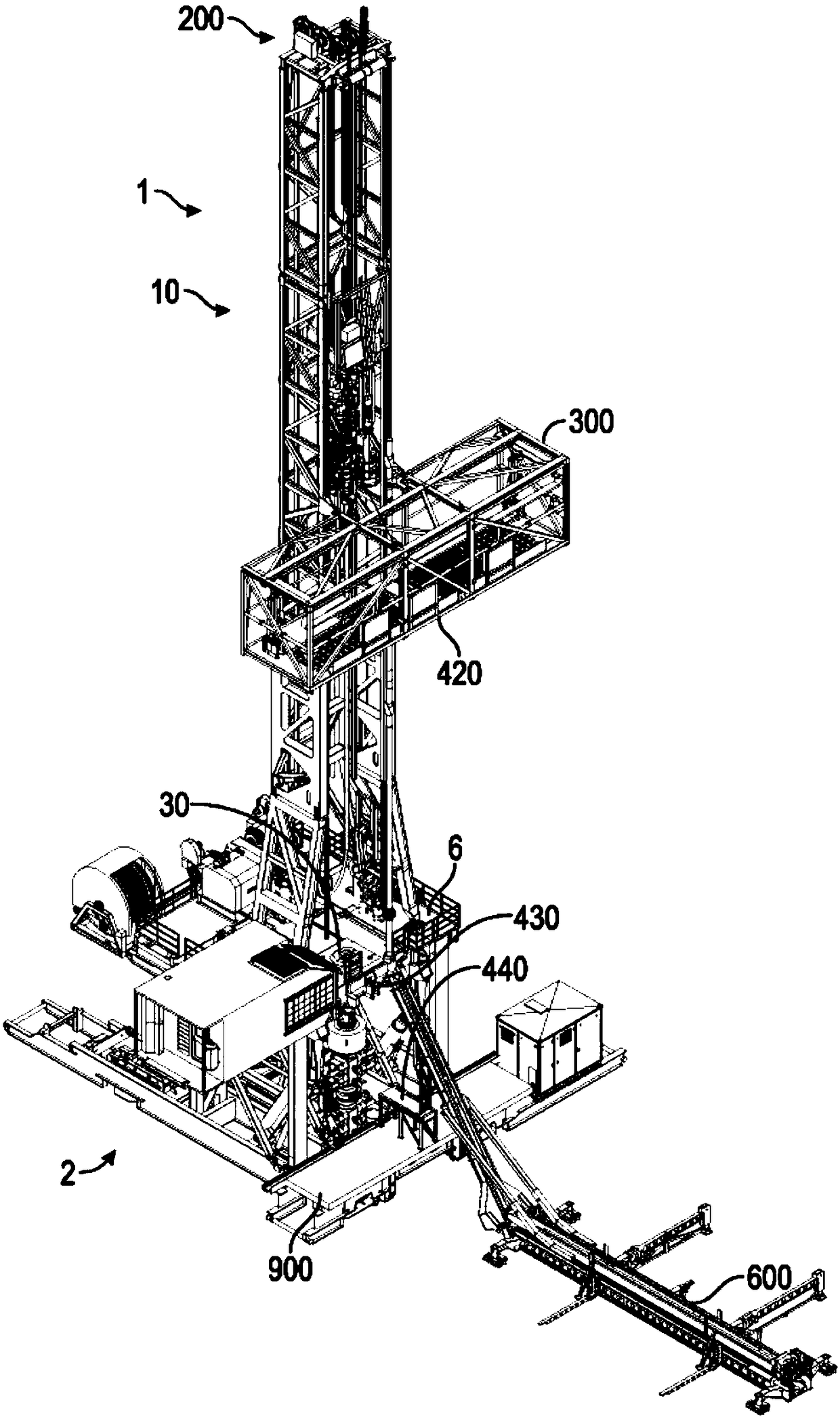
[0050] figure 1 One embodiment of the invention is shown. The following description is presented to enable one skilled in the art to make and use the invention, and is provided in the context of a particular application and its requirements. Various modifications to the disclosed embodiments will be readily apparent to those skilled in the art, and the generic principles defined herein may be applied to other embodiments and applications without departing from the spirit and scope of the invention . Thus, the present invention is not intended to be limited to the embodiments shown but is to be accorded the widest scope consistent with the principles and features disclosed herein.

[0051] figure 1 is an isometric...


PUM


Abstract

A retractable top drive for use with a drilling rig and process for operating a drilling rig. The retractable top drive comprises a dolly having a pair of mast rails in translatable relation to a mast, such as sliding. A yoke pivotally connects a torque tube to the dolly and the top drive is connected to the torque tube, so that a substantial portion of the top drive is positioned lower than a substantial portion of the dolly. An extendable actuator is connected between the dolly and the yoke to translate the top drive to / from the dolly. Torque is transferred from the top drive through the torque tube, yoke and dolly into the mast of the drill rig.

Description

[0001] continue statement [0002] This application claims priority to US Provisional Application No. 62 / 330,028, filed April 29, 2016. technical field [0003] The present disclosure relates to a drilling rig and system for moving drill pipe and drill collars into and out of a subterranean wellbore. In particular, the present invention relates to a retractable top drive (RTD) for use on a drilling rig, which is designed to significantly reduce the trip time of the drill string. Specifically, the present design is configured for use with a second crane that is translatably mounted to the same mast as the telescoping top drive. Background technique [0004] In the exploration for oil, gas and geothermal energy, drilling operations are used to form boreholes or wells in the ground. Drilling rigs used for subsurface exploration must be transported to the location where drilling activities are to begin. These locations are often located in remote, rugged terrain. Transportin...

Claims


Application Information

Patent Timeline
Patent Type & Authority Applications(China)
IPC IPC(8): E21B19/08E21B19/02E21B15/00
CPCE21B3/022E21B19/16
Inventor J.R.贝里R.梅茨M.A.奥尔
Owner SCHLUMBERGER TECH LTD BV
Why Eureka
Try Eureka