Anhydrous mechanical shaft sealing structure of bearing support for a side entry type stirrer

A bearing support and mechanical seal technology, which is applied in the direction of engine seals, mechanical equipment, engine components, etc., can solve the problems of mechanical seal skeleton oil seal damage, mechanical seal failure, poor support rigidity, etc., to ensure the use effect, good cooperation, The effect of strengthening rigidity

Inactive Publication Date: 2019-01-08
GUANGZHOU KAILILAI ELECTRICAL MACHINERY CO LTD
View PDF1 Cites 0 Cited by
  • Summary
  • Abstract
  • Description
  • Claims
  • Application Information

AI Technical Summary

Problems solved by technology

[0002] The side-entry mixer is to install the mixing device on the side wall of the equipment cylinder. The mixer on the mixer usually adopts the axial flow type, and most of them are push-type mixers. Under the condition of the same power consumption, the highest mixing effect can be obtained. , widely used in desulfurization, denitrification, and stirring of various large storage tanks or storage tanks. The mechanical seal of the prior art agitator with back flushing water device wastes water and when the on-site staff opens the back flushing water, the pressure If it is too large, the skeleton oil seal of the mechanical seal will be damaged, resulting in failure of the mechanical seal
At present, the agitator is supported by the bearing of the pulley deceleration belt, which inevitably requires the mechanical seal to have good bearing support. Poor support rigidity

Method used


Image

  • Anhydrous mechanical shaft sealing structure of bearing support for a side entry type stirrer
  • Anhydrous mechanical shaft sealing structure of bearing support for a side entry type stirrer

Examples


Embodiment Construction

[0018] The specific implementation manner of the present invention will be further described below in conjunction with the accompanying drawings. Wherein the same components are denoted by the same reference numerals. It should be noted that the words "front", "rear", "left", "right", "upper" and "lower" used in the following description refer to the directions in the drawings, and the words "inner" and "outer ” refer to directions towards or away from the geometric center of a particular part, respectively.

[0019] In order to make the content of the present invention more clearly understood, the technical solutions in the embodiments of the present invention will be clearly and completely described below in conjunction with the drawings in the embodiments of the present invention.

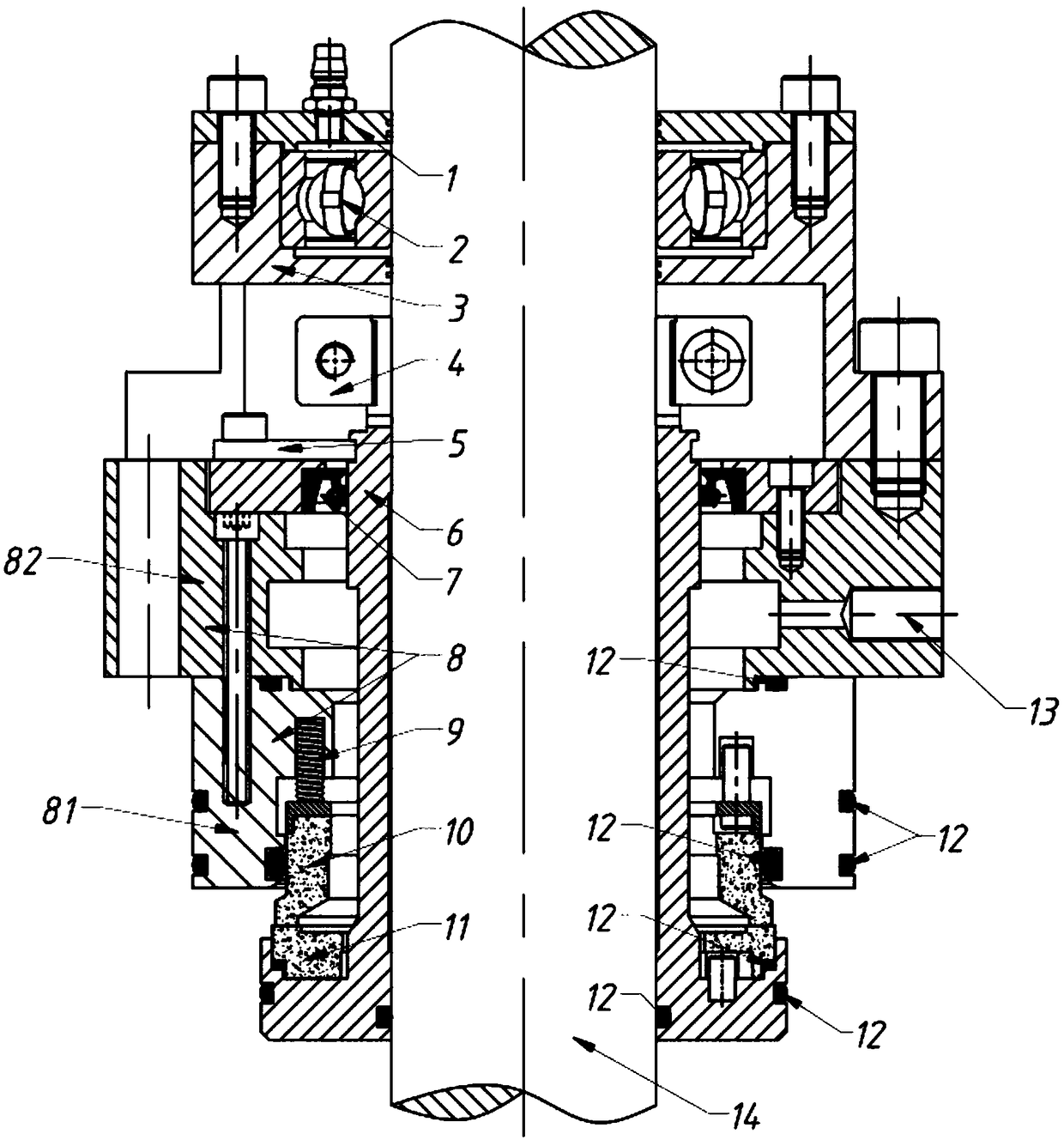
[0020] Such as figure 1 As shown, a waterless mechanical seal structure for a side-entry agitator bearing a shaft, including a shaft sleeve 6 with a shoulder at one end, a gland 8, a static ri...


PUM


Abstract

The invention provides an anhydrous mechanical shaft sealing structure of bearing support for a side entry type stirrer. The anhydrous mechanical shaft sealing structure of bearing support for the side entry type stirrer comprises a shaft sleeve with one end provided with a shoulder portion, a gland, a stationary ring and a movable ring. The shaft sleeve is connected to the shaft in a sleeving manner. The movable ring abuts against the shoulder portion of the shaft sleeve. The movable ring abuts against the end face of the stationary ring. The gland comprises a first gland and a second gland fixed together with the first gland. The gland is connected to the shaft sleeve in a sleeving manner, and the first gland is connected to the outer side of the stationary ring in a sleeving manner. A spring is arranged between the end of the stationary ring and the first gland. A framework oil seal is arranged between the second gland and the shaft sleeve. The end, far away from the first gland, ofthe second gland is provided with a drive ring. The shaft is connected with a bearing in a sleeved manner, wherein the bearing is fixed and limited through a bearing seat. The end, far away from thedrive ring, of the bearing seat is provided with a bearing head cover. The anhydrous mechanical shaft sealing structure of bearing support for the side entry type stirrer enhances the rigidity of thebearing for the shaft and can save water resource, and the service life of the device is prolonged.

Description

technical field [0001] The invention relates to the field of mechanical seals, in particular to a waterless mechanical seal structure for a bearing supporting shaft of a side-entry agitator. Background technique [0002] The side-entry mixer is to install the mixing device on the side wall of the equipment cylinder. The mixer on the mixer usually adopts the axial flow type, and most of them are push-type mixers. Under the condition of the same power consumption, the highest mixing effect can be obtained. , widely used in desulfurization, denitrification, and stirring of various large storage tanks or storage tanks. The mechanical seal of the prior art agitator with back flushing water device wastes water and when the on-site staff opens the back flushing water, the pressure If it is too large, the skeleton oil seal of the mechanical seal will be damaged, resulting in failure of the mechanical seal. At present, the agitator is supported by the bearing of the pulley decelerat...

Claims


Application Information

Patent Timeline
Patent Type & Authority Applications(China)
IPC IPC(8): F16J15/34
Inventor 凌贤金
Owner GUANGZHOU KAILILAI ELECTRICAL MACHINERY CO LTD
Why Eureka
Try Eureka