Deep soil fertilizer applicator

A deep fertilization and soil technology, applied in fertilization devices, manure treatment, fertilizer distributors, etc., can solve the problems of low labor intensity, poor fertilization effect, and all the soil is pounded out, so as to improve work efficiency, reduce difficulty, and improve fertilization. the effect of

Active Publication Date: 2019-01-11
杭州市临安区农林技术推广中心 +1
View PDF6 Cites 11 Cited by
  • Summary
  • Abstract
  • Description
  • Claims
  • Application Information

AI Technical Summary

Problems solved by technology

[0004] In the above-mentioned patent documents, by manually rotating the rotary block, the excavation screw-in rod is screwed into the soil for drilling, which avoids the previous manual large-scale trenching and deep-burying fertilization method, and the labor intensity is low, and the soil screw-in When the rod is drilled to a certain depth, the lower end orifice of the eccentric feeding channel on the conical surface of the conical end of the lower end of the excavating rod is used to connect the excavated soil, and the fertilizer is poured into the feeding hopper, and the fertilizer is fed along the eccentric The hole is transported to the root system of the plant to realize fertilization; however, in this scheme, the soil is easy to enter the inside of the excavation screw-in rod along the eccentric feeding hole. All smashed out, resulting in poor fertilization effect

Method used


Image

  • Deep soil fertilizer applicator
  • Deep soil fertilizer applicator
  • Deep soil fertilizer applicator

Examples


Embodiment Construction

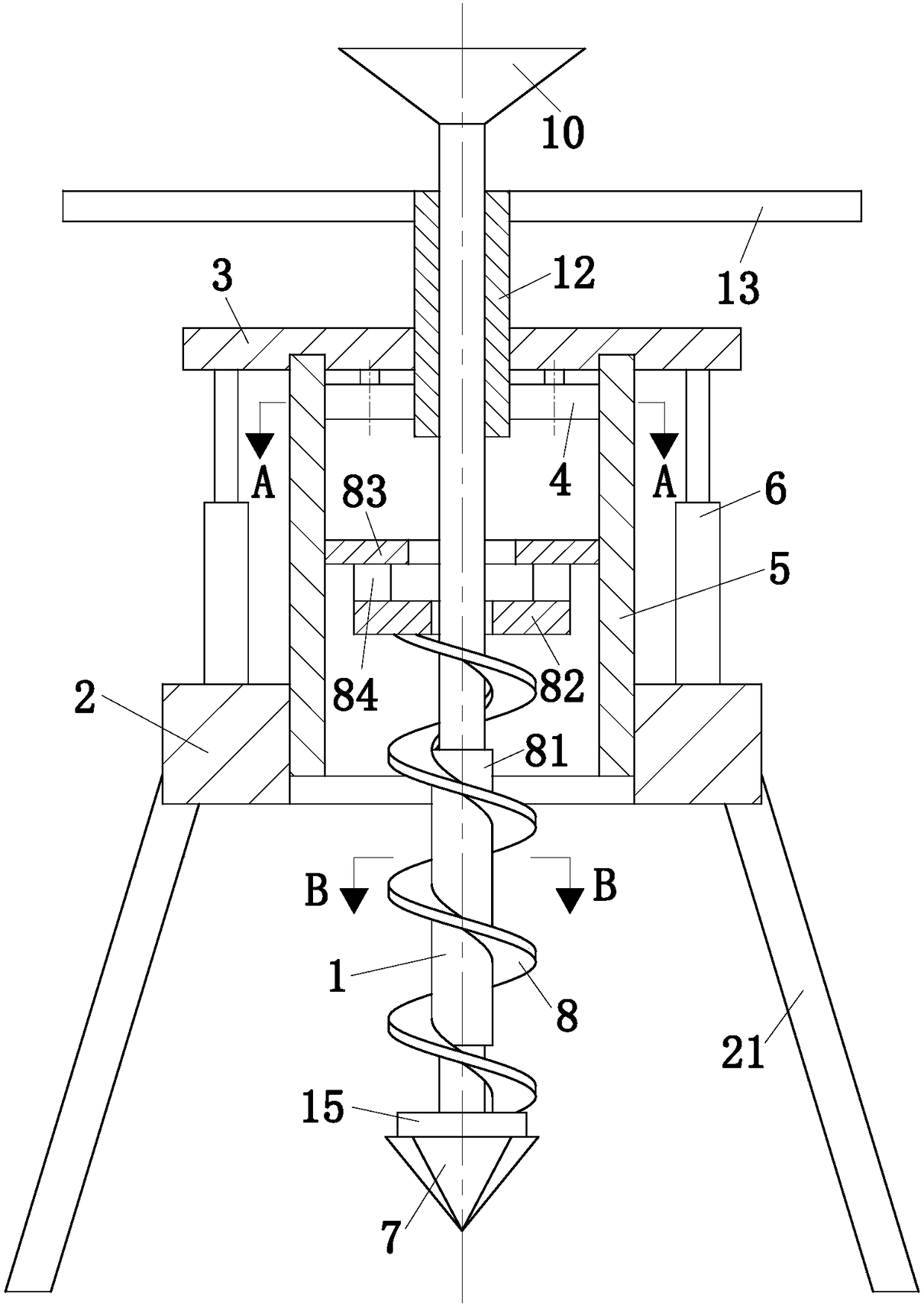
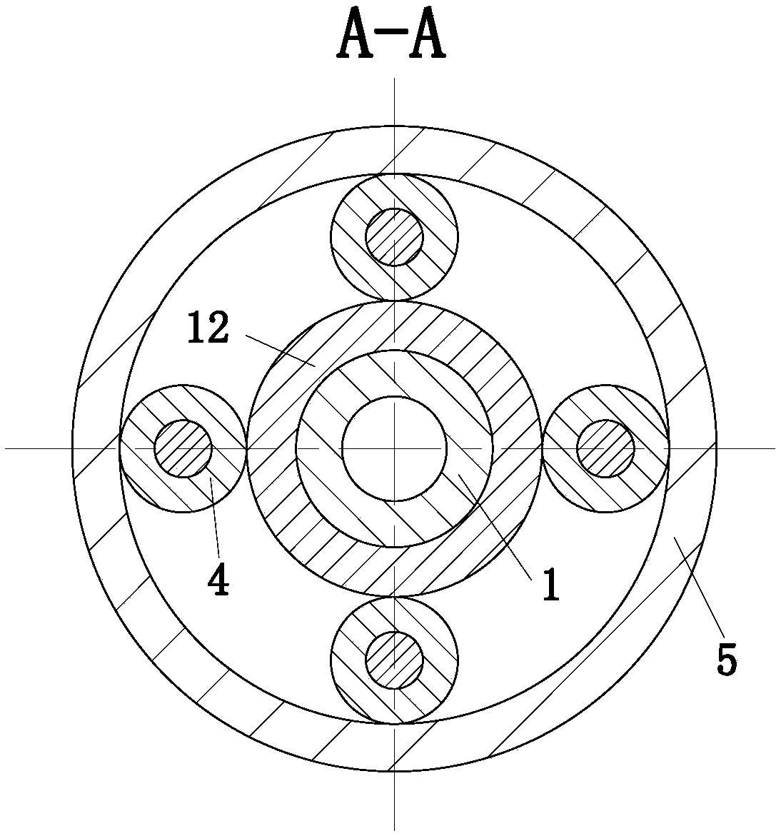
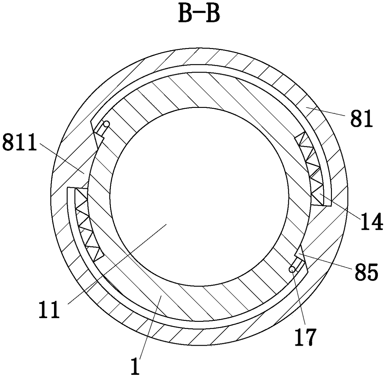
[0022] use Figure 1-Figure 5 A deep soil fertilization device according to an embodiment of the present invention will be described as follows.

[0023] Such as Figure 1-Figure 5As shown, a deep soil fertilization device according to the present invention includes a digging rod 1, a fixed frame 2, a limit plate 3, a planetary gear 4, an inner ring gear 5 and a cylinder 6, and the lower end of the digging rod 1 is set There is a conical block 7, and the outer surface of the digging rod 1 is provided with a spiral piece 8, and the screw piece 8 is used to transmit the soil outwards, and the inside of the digging rod 1 is provided with a feeding passage 11, and the upper end of the feeding passage 11 is connected to the digging rod. The upper surfaces of 1 are connected, the lower end of the conveying channel 11 extends downward to the conical surface of the conical block 7, and a discharge port 71 is formed on the surface of the conical block 7, and the upper end of the diggi...


PUM


Abstract

The invention belongs to the technical field of agricultural machines, and concretely relates to a deep soil fertilizer applicator. The deep soil fertilizer applicator comprises an earth cutting rod,a fixed frame, a limiting plate, planetary gears, an inner gear ring and cylinders, and the outer surface of the earth cutting rod is coaxially fixedly provided with a sleeve; the sleeve is rotatablymounted on the limit plate; the limiting plate is horizontally arranged above the fixed frame, the limiting plate is located below the rotary handle, and the limiting plate is connected with the fixedframe through the plurality of vertically-arranged cylinders; the number of planetary gears is four or more, and the planetary gears are engaged with a toothed structure of the sleeve; the inner gearring is rotatably mounted on the limiting plate, the inner gear ring is engaged with the planetary gears, and the inner gear ring is connected with and a through hole-through hole threaded structure;an inner cylinder is vertically arranged in the axial center position of a screw panel; and the inner cylinder is fixedly connected with the screw panel, the outer circumferential surface of a part,in contact with the inner cylinder, of the earth cutting rod is provided with sliding grooves, bosses are arranged on the inner wall of a second through hole of the inner cylinder, and the bosses arepositioned in the sliding grooves. The deep soil fertilizer applicator can realize smooth fertilization, and has a high working efficiency.

Description

technical field [0001] The invention belongs to the technical field of agricultural machinery, in particular to a deep soil fertilization device. Background technique [0002] At present, the existing fertilization device is aimed at plowing the field and then fertilizing by watering. This traditional fertilizing method is only suitable for common crops growing in large areas and plants with shallow root systems, such as trees. For plants with deep root systems, the traditional fertilization device is not suitable. It can only be artificially dug deep and buried, which is troublesome and inconvenient. The labor intensity is high, and the fertilization position is not accurate. [0003] Patent document: A deep soil fertilization device Application number: 201510085841.1 [0004] In the above-mentioned patent documents, by manually rotating the rotary block, the excavation screw-in rod is screwed into the soil for drilling, which avoids the previous manual large-scale trenchi...

Claims


Application Information

Patent Timeline
Patent Type & Authority Applications(China)
IPC IPC(8): A01C5/02A01C15/02
CPCA01C5/02A01C15/02
Inventor 邬奇峰秦华黄仨仨陈英霞王方刘波
Owner 杭州市临安区农林技术推广中心
Why Eureka
Try Eureka