Flotation machine

A flotation machine and flotation chamber technology, which is applied in the field of flotation machines, can solve the problems of poor flotation effect and difficult to fully mix ore pulp, etc., and achieve the effects of good mixing, rich design and increasing eddy current area.

Active Publication Date: 2020-08-21
CHINA SHENHUA ENERGY CO LTD +1
View PDF6 Cites 0 Cited by
  • Summary
  • Abstract
  • Description
  • Claims
  • Application Information

AI Technical Summary

Problems solved by technology

[0003] At present, the most commonly used is the mechanical agitation flotation machine, the mechanical agitation flotation machine uses a straight rod to stir the pulp, it is difficult to fully mix the pulp, resulting in poor flotation effect

Method used


Image

  • Flotation machine
  • Flotation machine
  • Flotation machine

Examples


Embodiment 1

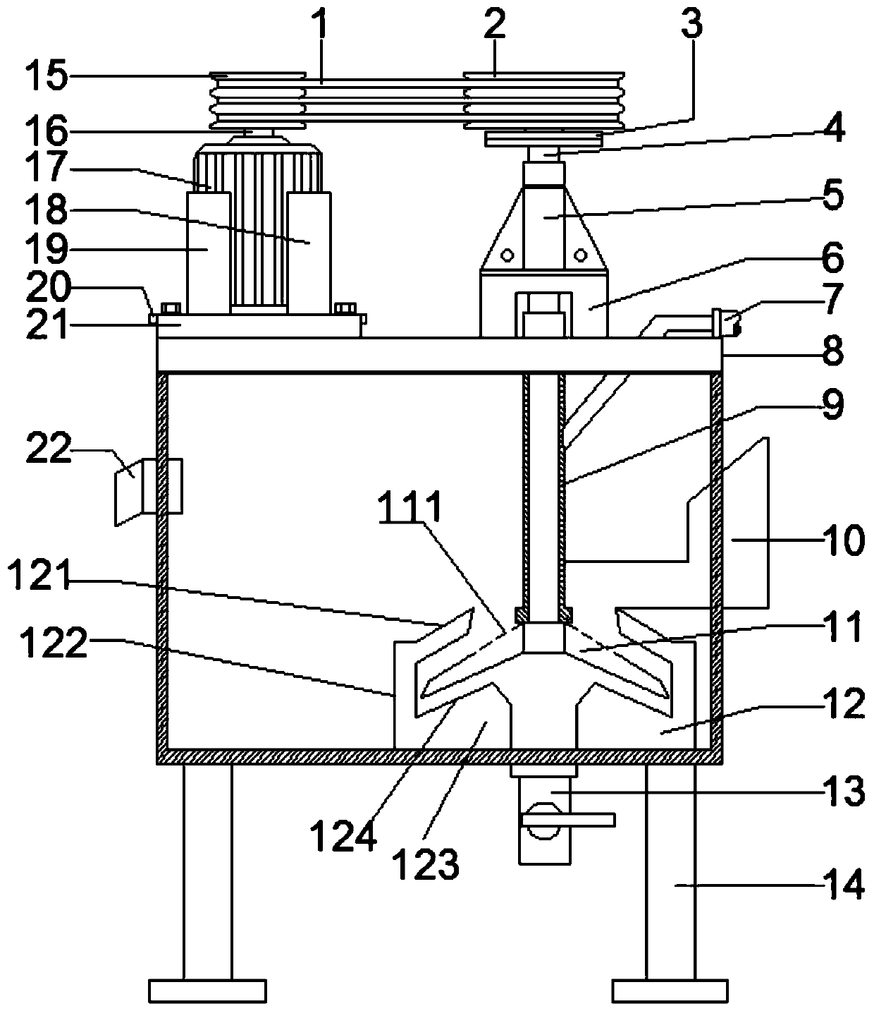
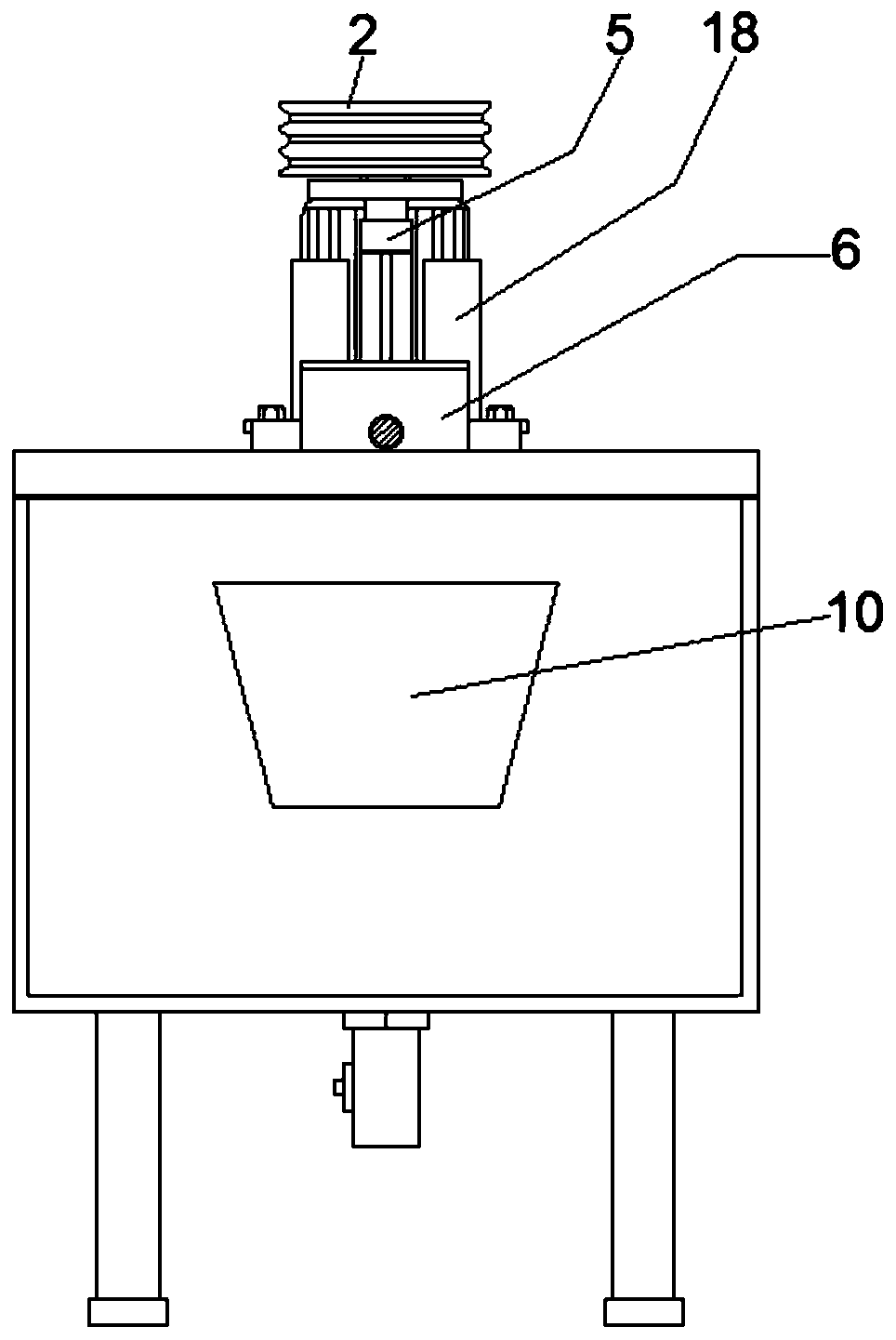
[0021] figure 1 Show the structural representation of the flotation machine of the embodiment of the present invention, figure 2 A side view of a flotation machine according to an embodiment of the invention is shown. Such as Figure 1-2 As shown, the flotation machine provided by the embodiment of the present invention includes: a driving part, a stirring part and a device body 8 .

[0022] The device body 8 is hollow. The stirring part includes a rotating shaft 4 and a stirring cover 11 , the rotating shaft 4 is installed on the device body 8 , and the rotating shaft 4 is fixedly connected to the first end of the stirring cover 11 .

[0023] In this embodiment, the rotating shaft 4 is detachably connected to the stirring cover 11 to facilitate maintenance and replacement.

[0024] The outer diameter of the first end of the stirring mantle 11 is smaller than the outer diameter of the second end thereof. The opening of the stirring cover 11 faces the bottom of the device...

Embodiment 2

[0029] On the basis of the first embodiment above, optionally, as figure 1 As shown, the stirring mantle 11 is provided with an air outlet 111, which can discharge the gas in the stirring mantle 11 to the outside of the stirring mantle 11 to improve the flotation effect.

[0030] Such as figure 1 As shown, there are multiple exhaust air holes 111 on the stirring shell 11, and the multiple exhaust air holes 111 are evenly arranged along the circumferential direction of the stirring shell 11 to further improve the flotation effect.

[0031] Preferably, a flotation chamber 12 is provided at the bottom of the device body 8 .

[0032] The flotation chamber 12 includes a chamber body 122 and a chamber cover 121, and the chamber cover 121 is covered on the chamber body. In this embodiment, the flotation chamber 12 is integrally formed.

[0033] The cavity cover 121 is provided with a through hole, and the stirring cover 11 is positioned in the cavity 122 through the through hole, a...


PUM


Abstract

An embodiment of the invention discloses a flotation machine. The flotation machine comprises a driving part, a stirring part and a device body; the device body is hollow; the stirring part comprisesa rotating shaft and a stirring cover; the rotating shaft is rotationally mounted on the device body and is fixedly connected with the first end of the stirring cover; the outer diameter of the firstend of the stirring cover is smaller than that of the second end of the stirring cover; and the driving part drives the stirring cover through the rotating shaft to rotate inside the device body. By the aid of the flotation machine, the vortex area can be increased, so that pulp can be better mixed, and the flotation effect can be improved.

Description

technical field [0001] The invention relates to the technical field of coal mines, in particular to a flotation machine. Background technique [0002] The flotation machine is the abbreviation of the flotation concentrator, which refers to the mechanical equipment that completes the flotation process. In the flotation machine, the ore pulp treated by adding chemicals is agitated and inflated, so that some of the ore particles are selectively fixed in the air bubbles. Floating to the surface of the pulp is scraped off to form a foam product, and the rest is retained in the pulp to achieve the purpose of separating minerals; there are many structural forms of flotation machines. [0003] At present, the most commonly used is the mechanical agitation flotation machine, which uses a straight rod to agitate the pulp, which is difficult to fully mix the pulp, resulting in poor flotation effect. Contents of the invention [0004] In view of this, an embodiment of the present inv...

Claims


Application Information

Patent Timeline
Patent Type & Authority Patents(China)
IPC IPC(8): B03D1/14
CPCB03D1/14
Inventor 潘月军郝国庆王斌冯来宏田娜陈乐党锐刚韩喜龙曾红久
Owner CHINA SHENHUA ENERGY CO LTD
Why Eureka
Try Eureka