Clamping jaw special for wheel hub coating

A technique of painting and clamping jaws, applied in the field of clamping jaws, can solve the problems of many workers transferring parts, high physical labor intensity, and inability to meet the requirements, and achieve the effects of wide application range, longer stroke, and firm grasping.

Inactive Publication Date: 2019-01-11
广东创智智能装备有限公司
View PDF10 Cites 0 Cited by
  • Summary
  • Abstract
  • Description
  • Claims
  • Application Information

AI Technical Summary

Problems solved by technology

[0002] In traditional automobile wheel manufacturing, the transfer of wheel coating is usually carried out manually. However, with the rapid development of the automobile industry, automobile wheel manufacturing has also developed rapidly, and manual transfer of wheels can no longer meet production requirements.
The main reasons are as follows: 1. The weight of the wheel hub is 15-30KG. Using manual transfer, the physical labor intensity of the workers is too high; 2. The major wheel hub manufacturers have increased the speed of the production line. The original 1.5-meter line speed has been increased to 3 meters, and some even reached 4 meters. , so that the number of transfer parts is more, more transfer workers are needed, and the cost of manpower input is increased; 3. The transfer operation position is generally closer to the drying line and curing furnace, and the temperature in summer can reach 40-50 degrees. Large marks left on the hub
[0003] In order to solve the above problems, someone designed a product that automatically transfers the jaws. At present, the mature jaws on the market are relatively small, mainly for light and short-stroke products, which cannot meet the use of large and heavy wheels, and some even can. For the transfer of hubs, there are also problems of large footprints and insufficient grip, and it is difficult to meet the requirements of long-stroke and universal hub transfer applications for hubs of different diameters

Method used


Image

  • Clamping jaw special for wheel hub coating
  • Clamping jaw special for wheel hub coating
  • Clamping jaw special for wheel hub coating

Examples


Embodiment Construction

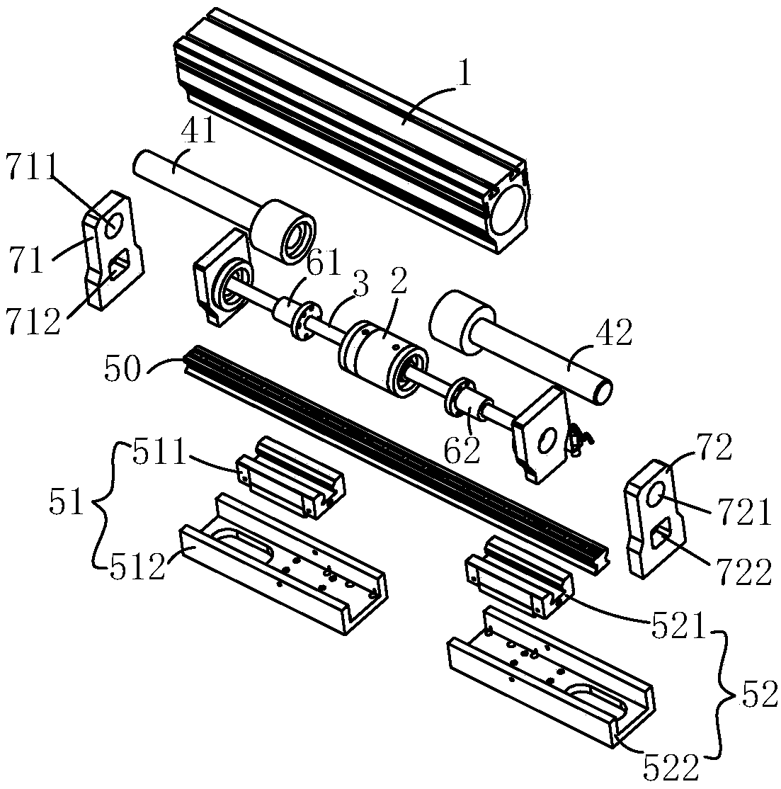
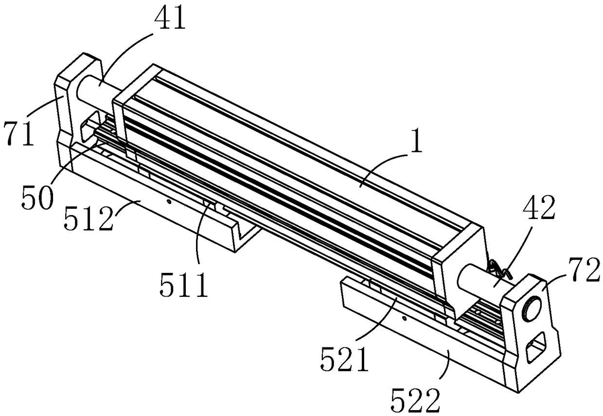
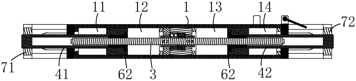
[0015] In the description of the present invention, it should be understood that the orientation or positional relationship indicated by the terms "center", "upper", "lower", "front", "rear", "left", "right" etc. are based on The orientation or positional relationship shown in the drawings is only for the convenience of describing the present invention and simplifying the description, and does not indicate or imply that the referred device or element must have a specific orientation, be constructed and operated in a specific orientation, and therefore cannot be understood as Limitations on the Invention. In addition, the terms "first" and "second" are used for descriptive purposes only, and should not be understood as indicating or implying relative importance.

[0016] In the description of the present invention, it should be noted that unless otherwise specified and limited, the terms "installation", "connection" and "connection" should be understood in a broad sense, for ex...


PUM


Abstract

The invention relates to a clamping jaw special for wheel hub coating. The clamping jaw comprises a cylinder block, a slide rail arranged below the cylinder block, a first sliding device and a secondsliding device, the first sliding device and the second sliding device are arranged on the slide rail, the inner portion of the cylinder block is provided with a ball screw, a bearing structure is arranged on the outer surface of the ball screw, a first piston structure and a second piston structure are arranged on the two sides of the bearing structure, the first piston structure and the first sliding device are connected, the second piston structure is connected to the second sliding device, and the two piston structures are driven by rotation of the ball screw to synchronously move, and thefirst sliding device and the second sliding device are driven to do synchronous movement. The clamping jaw has the advantages of larger clamping force, larger gripping force, smaller impression marksand the wider application range.

Description

technical field [0001] The invention relates to the field of clamp jaws, in particular to a special clamp jaw for wheel hub coating. Background technique [0002] In traditional automobile wheel manufacturing, the transfer of wheel coating is usually carried out manually. However, with the rapid development of the automobile industry, automobile wheel manufacturing has also developed rapidly, and manual transfer of wheels can no longer meet the production requirements. The main reasons are as follows: 1. The weight of the wheel hub is 15-30KG. Using manual transfer, the physical labor intensity of the workers is too high; 2. The major wheel hub manufacturers have increased the speed of the production line. The original 1.5-meter line speed has been increased to 3 meters, and some even reached 4 meters. , so that the number of transfer parts is more, more transfer workers are needed, and the cost of manpower input is increased; 3. The transfer operation position is generally ...

Claims


Application Information

Patent Timeline
Patent Type & Authority Applications(China)
IPC IPC(8): B05C13/00B05C13/02
CPCB05C13/00B05C13/02
Inventor 严长志许仕建
Owner 广东创智智能装备有限公司
Why Eureka
Try Eureka