
Perforating machine

A punching machine and sliding hole technology, which is applied in the field of punching machines, can solve the problems of high cost, high degree of automation, and inapplicability to the processing of mechanical parts for small enterprises, and achieve the effect of low cost

Pending Publication Date: 2019-01-11
TIANJIN LONGCHI MACHINERY MFG CO LTD
View PDF7 Cites 8 Cited by
  • Summary
  • Abstract
  • Description
  • Claims
  • Application Information

AI Technical Summary

Problems solved by technology

[0004] The purpose of the present invention is to solve the problem that the punching machine in the prior art occupies a relatively large space, requires a relatively high degree of automation, and requires a high cost, and is not suitable for the processing of mechanical parts of small enterprises, and proposes a punching machine

Method used


Image

  • Perforating machine
  • Perforating machine

Examples


Embodiment Construction

[0019] The following will clearly and completely describe the technical solutions in the embodiments of the present invention with reference to the accompanying drawings in the embodiments of the present invention. Obviously, the described embodiments are only some, not all, embodiments of the present invention.

[0020] In describing the present invention, it should be understood that the terms "upper", "lower", "front", "rear", "left", "right", "top", "bottom", "inner", " The orientation or positional relationship indicated by "outside", etc. is based on the orientation or positional relationship shown in the drawings, and is only for the convenience of describing the present invention and simplifying the description, rather than indicating or implying that the referred device or element must have a specific orientation, so as to Specific orientation configurations and operations, therefore, are not to be construed as limitations on the invention.

[0021] refer to Figure ...


PUM


Abstract

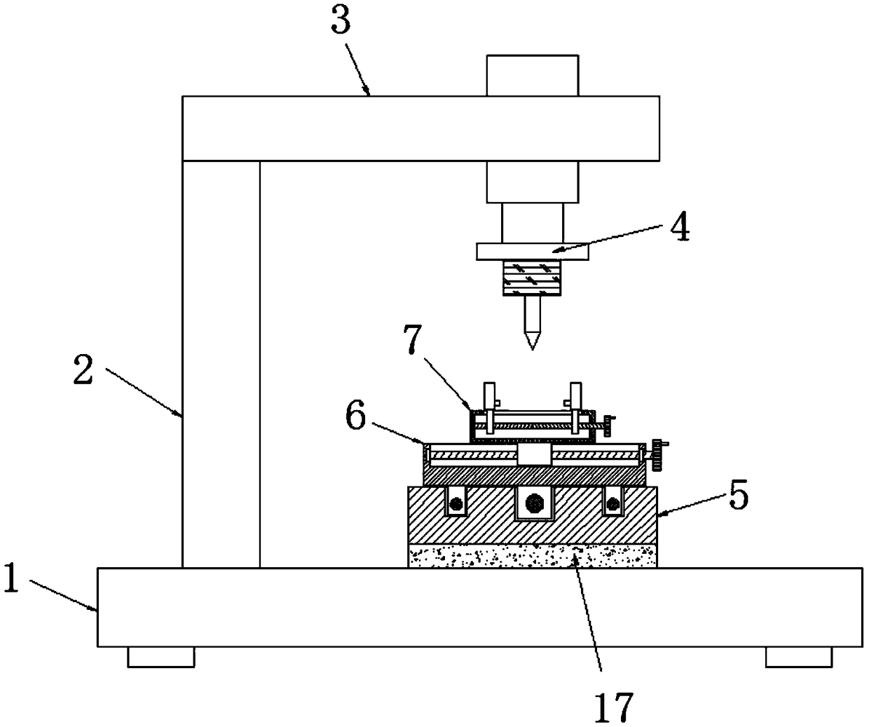
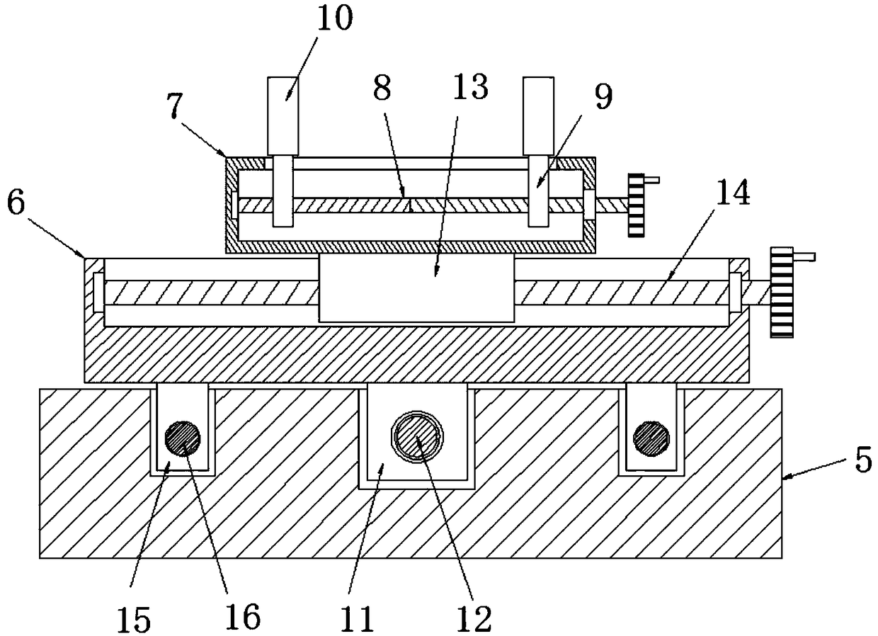
The invention discloses a perforating machine comprising a workbench. A stand column is vertically and fixedly connected with one side of the upper end of the workbench; the upper end of the stand column is fixedly connected with a cross arm; a punching device is fixedly arranged at the lower end of the cross arm; a first supporting board is fixedly arranged at the position, under the punching device, of the upper end of the workbench; a second supporting board is movably arranged at the upper end of the first supporting board; a clamping table is movably arranged at the upper end of the second supporting board; a cavity is transversely arranged inside the clamping table; a bidirectional screw rod is transversely arranged inside the cavity; the two ends of the bidirectional screw rod are rotationally connected with the two sides of the cavity through first rolling bearings separately; and one end of the bidirectional screw rod extends out of the clamping table and is fixedly connectedwith a first rotary wheel. Clamped workpieces are driven to move in a comprehensive mode, different positions of the workpieces are punched through the punching device conveniently, needed cost is low, and the perforating machine is suitable for machining mechanical parts of small enterprises.

Description

technical field [0001] The invention relates to the technical field of mechanical processing equipment, in particular to a punching machine. Background technique [0002] Machining refers to the process of changing the shape or performance of a workpiece through a mechanical device. According to the difference in processing methods, it can be divided into cutting processing and pressure processing. When performing mechanical processing, mechanical equipment is an important tool. Among them, the punching machine is a tool for punching holes in the mold. The automatic punching machine punches and prints positioning holes. The whole action is done in one go, fast, accurate and efficient. [0003] However, for the punching machines currently on the market, most of the punching machine fixtures are fixed on the workbench. When punching holes at different positions on the workpiece, it is necessary to adjust the position between the punch and the workpiece. There is a driving dev...

Claims


Application Information

Patent Timeline
IPC IPC(8): B21D28/24B21D43/00
CPCB21D28/24B21D43/003
Inventor 项福忠
Owner TIANJIN LONGCHI MACHINERY MFG CO LTD
Learn More