
Side glue feeding injection mold

An injection mold and side-feeding glue technology, which is applied in the field of injection molding, can solve problems such as waste of raw materials in the flow channel, and achieve the effects of reducing waste of raw materials, avoiding interference, and shortening the length

Pending Publication Date: 2019-01-11
SHENZHEN SILVER BASIS TECH
View PDF0 Cites 0 Cited by
  • Summary
  • Abstract
  • Description
  • Claims
  • Application Information

AI Technical Summary

Problems solved by technology

[0004] The main purpose of the present invention is to propose a side-feeding plastic injection mold, which aims to solve the technical problem of serious waste of raw materials in the flow channel in the existing injection molds

Method used


Image

  • Side glue feeding injection mold
  • Side glue feeding injection mold
  • Side glue feeding injection mold

Examples


Embodiment Construction

[0029] The following will clearly and completely describe the technical solutions in the embodiments of the present invention with reference to the accompanying drawings in the embodiments of the present invention. Obviously, the described embodiments are only part of the embodiments of the present invention, not all of them. Based on the embodiments of the present invention, all other embodiments obtained by persons of ordinary skill in the art without creative efforts fall within the protection scope of the present invention.

[0030] It should be noted that if there is a directional indication (such as up, down, left, right, front, back...) in the embodiment of the present invention, the directional indication is only used to explain the position in a certain posture (as shown in the accompanying drawing). If the specific posture changes, the directional indication will also change accordingly.

[0031] In addition, if there are descriptions involving "first", "second" and ...


PUM


Abstract

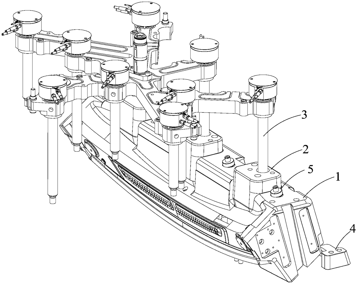
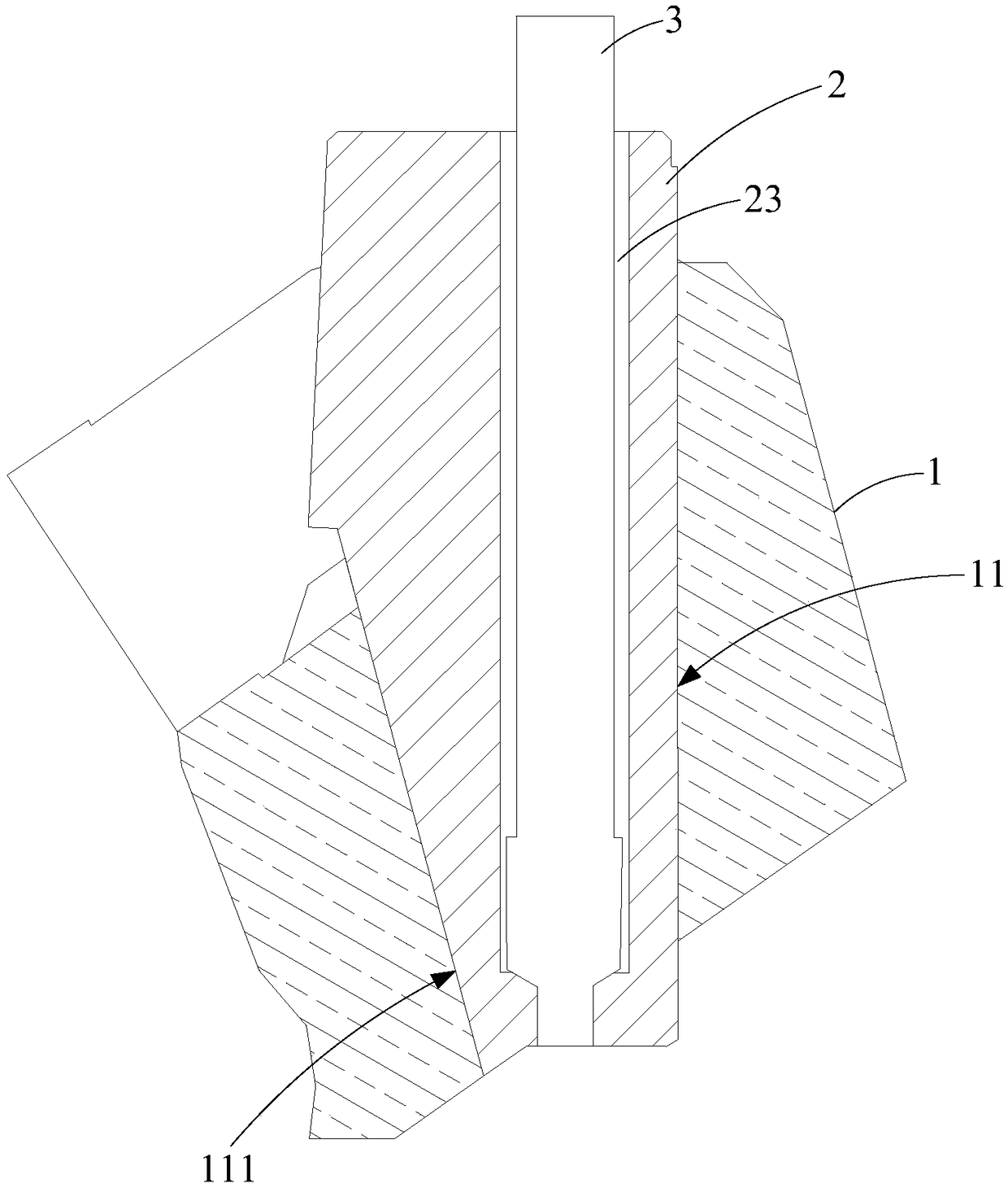
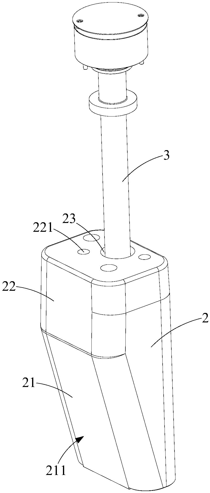
The invention discloses a side glue feeding injection mold comprising a movable mold, a fixed mold, a side core-pulling slider, a hot nozzle insert and a hot nozzle. The side core-pulling slider is arranged at a side glue inlet of the movable mold and is provided with a guide channel. The guide channel is provided with an inclined wall. The hot nozzle insert is arranged in the guide channel and isprovided with a guide wall. The guide wall is attached to the inclined wall so that the hot nozzle insert and the side core-pulling slider can slide relatively. A giving-way channel is formed in thehot nozzle insert in a through mode. The hot nozzle is arranged on the fixed mold and penetrates through the giving-way channel to communicate with the side glue inlet. The side glue feeding injectionmold provided by the technical scheme of the invention has the advantages that product precision is high, and raw materials are wasted little.

Description

technical field [0001] The invention relates to the technical field of injection molding, in particular to a side-feeding plastic injection mold. Background technique [0002] Injection molding refers to a process in which molten material is injected into the mold cavity, and the product is obtained after cooling the material. Generally speaking, the mold includes a fixed mold and a movable mold, and the fixed mold and the movable mold are aligned to form a cavity. In the production of flat-plate products, in order to avoid defects such as curling, warping, and burrs, the glue inlet of the product is generally set at the bottom of the product, that is, the bottom of the cavity, and there is a flow channel between the glue inlet and the cavity Connected, the fixed or movable mold of this type of mold will be equipped with movable side core-pulling sliders. When the mold is opened, the side core-pulling sliders will slide to the side and separate from the product. [0003] G...

Claims


Application Information

Patent Timeline
Patent Type & Authority Applications(China)
IPC IPC(8): B29C45/26B29C45/27B29C45/33
CPCB29C45/26B29C45/27B29C45/33B29C45/332
Inventor 高国利李芳陈祖苗段志平
Owner SHENZHEN SILVER BASIS TECH
Learn More