
Cylindrical lithium ion battery transferring and clamping device and battery transferring and clamping technology

A lithium-ion battery, transfer clip technology, applied in the directions of transportation and packaging, conveyor objects, etc., can solve the problems of inconvenient adjustment, asynchronous clamping, high work cost, small use range, etc., and achieve the effect of avoiding falling

Active Publication Date: 2019-01-11
泰州亿丰达电器有限公司
View PDF7 Cites 7 Cited by
  • Summary
  • Abstract
  • Description
  • Claims
  • Application Information

AI Technical Summary

Problems solved by technology

[0003] In order to make up for the deficiencies in the prior art, the present invention provides a cylindrical lithium-ion battery transport clamping device and battery transport clamping process, the present invention can solve the problems of small use range and adjustment in the current cylindrical lithium-ion battery transport process. Inconvenient, prone to battery drop, unsynchronized clamping and high work costs, etc., can realize the automatic clamping function of cylindrical lithium-ion batteries. It has a wide range of use, easy adjustment, and the battery is not easy to drop. Advantages of synchronous clamping and cost saving

Method used


Image

  • Cylindrical lithium ion battery transferring and clamping device and battery transferring and clamping technology
  • Cylindrical lithium ion battery transferring and clamping device and battery transferring and clamping technology
  • Cylindrical lithium ion battery transferring and clamping device and battery transferring and clamping technology

Examples


Embodiment Construction

[0023]In order to make the technical means, creative features, goals and effects achieved by the present invention easy to understand, the present invention will be further described below in conjunction with specific illustrations.

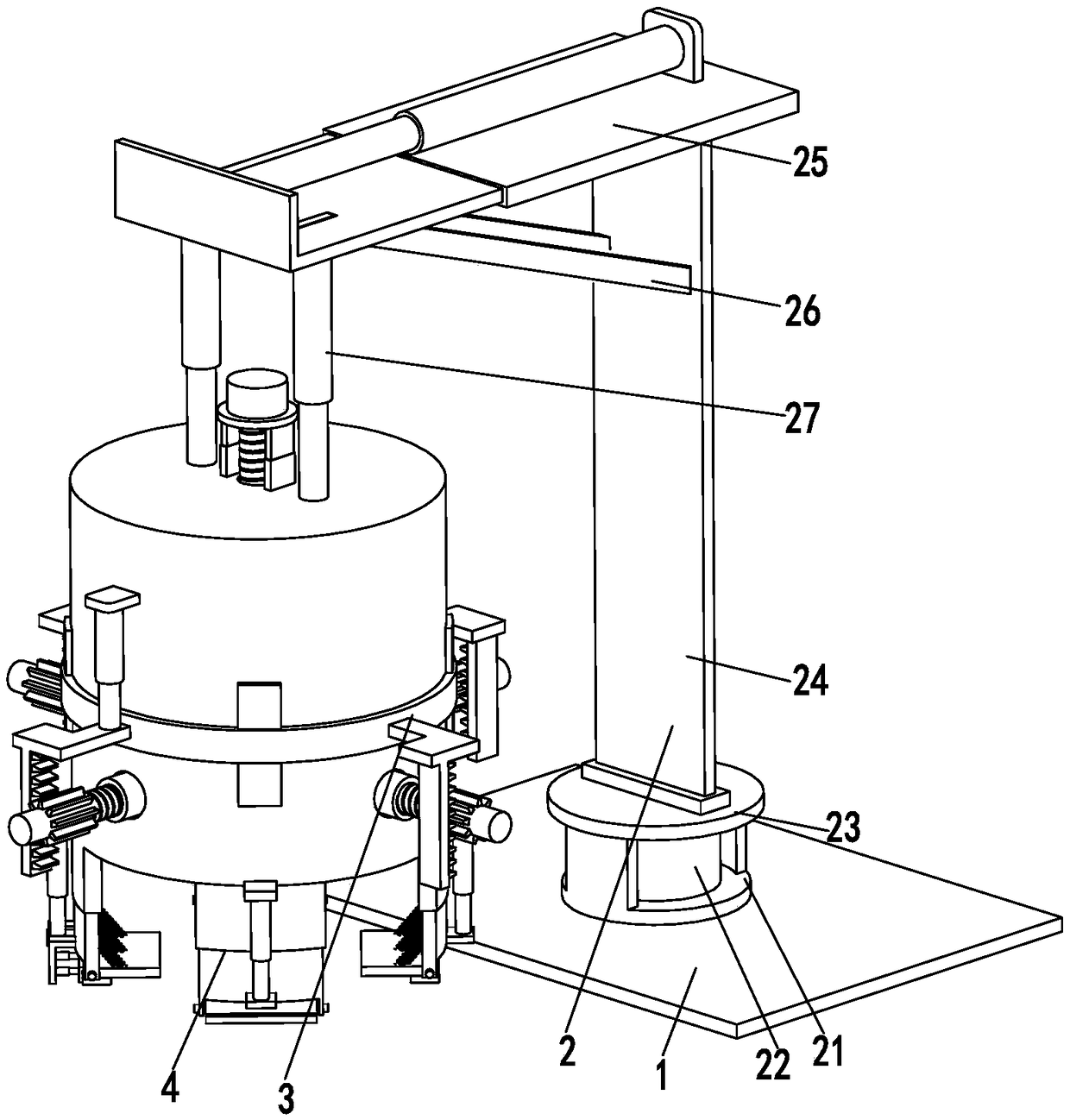
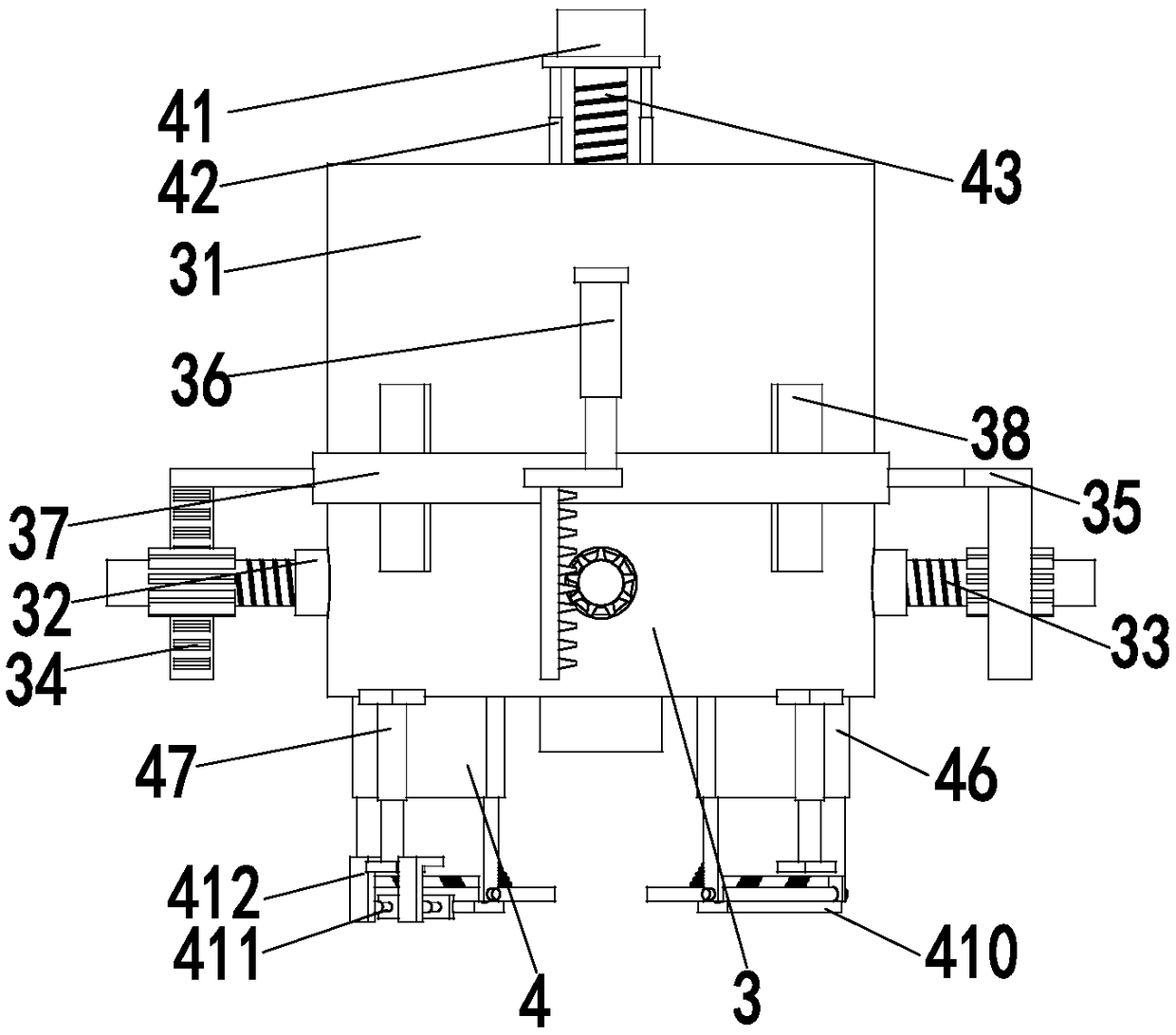
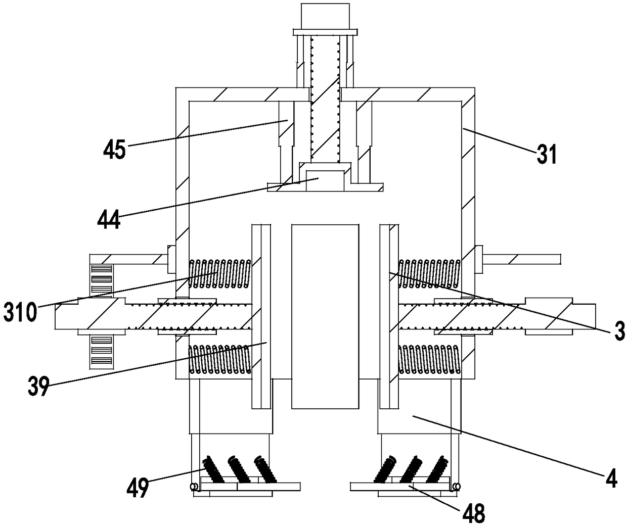
[0024] Such as Figure 1 to Figure 3 As shown, a cylindrical lithium-ion battery transfer clamping device includes a bottom plate 1, an adjustment mechanism 2, a clamping mechanism 3 and an auxiliary mechanism 4. An adjustment mechanism 2 is installed on the bottom plate 1, and a clip is installed at the lower end of the adjustment mechanism 2. Take mechanism 3, auxiliary mechanism 4 is installed on the side wall of gripping mechanism 3; Wherein:

[0025] The adjustment mechanism 2 includes a support base 21, a rotating motor 22, a rotating plate 23, a support frame 24, a telescopic adjustment frame 25, a support rod 26 and a lift cylinder 27, the support base 21 is installed on the base plate 1, and the rotation motor 22 passes through the motor...


PUM


Abstract

The invention relates to a cylindrical lithium ion battery transferring and clamping device and a battery transferring and clamping technology. The cylindrical lithium ion battery transferring and clamping device comprises a bottom plate, an adjusting mechanism, a clamping mechanism and an auxiliary mechanism. The adjusting mechanism is installed on the bottom plate. The clamping mechanism is installed at the lower end of the adjusting mechanism. The auxiliary mechanism is installed on the side wall of the clamping mechanism. The adjusting mechanism comprises a supporting seat, a rotating motor, a rotating plate, a supporting frame, a telescopic adjusting frame, a supporting rod and a lifting air cylinder. The clamping mechanism comprises an installation cylinder, a sleeve, an adjusting rod, a rack, an installation plate, an adjusting air cylinder, a connecting ring, a guide rail, a pressing plate and a buffering spring. By means of the cylindrical lithium ion battery transferring andclamping device and the battery transferring and clamping technology, the problems that the use range is small, adjusting is not convenient, a battery is likely to fall, clamping is not synchronous, and the work cost is high in the current cylindrical lithium ion battery transferring process can be solved; an automatic clamping function can be achieved on cylindrical lithium ion batteries; and thebeneficial effects that batteries are not likely to fall, clamping can be synchronous, and the work cost is saved are achieved.

Description

technical field [0001] The invention relates to the field of battery clamping equipment, in particular to a cylindrical lithium-ion battery transfer clamping device and a battery transfer clamping process. Background technique [0002] Lithium-ion battery is a secondary battery (rechargeable battery), which mainly relies on the movement of lithium ions between the positive and negative electrodes to work. Common lithium-ion batteries are mostly rectangular parallelepiped or cylindrical. When clamping a cylindrical battery, basically multiple driving mechanisms are used to drive different jaws to fix the battery surface. When the driving mechanisms operate differently, it is easy to cause incorrect clamping. If the battery is not firmly in place, the battery may fall, which may cause damage to the battery or explosion of the battery, which increases the cost of work and the danger in the work process. In addition, the existing cylindrical lithium battery clamping equipment i...

Claims


Application Information

Patent Timeline
IPC IPC(8): B65G47/90
CPCB65G47/902
Inventor 缪心怡
Owner 泰州亿丰达电器有限公司
Learn More