High-efficiency safety material conveying fan

A conveying fan, safe technology, applied in conveyors, conveying bulk materials, transportation and packaging, etc., can solve the problems of low exhaust gas efficiency and easy eddy current generation, so as to improve blowing efficiency, prevent eddy current generation, and facilitate installation Effect

Pending Publication Date: 2019-01-11
ZHENJIANG DANTU DISTRICT FOOD FACTORY
View PDF8 Cites 2 Cited by
  • Summary
  • Abstract
  • Description
  • Claims
  • Application Information

AI Technical Summary

Problems solved by technology

[0005] Aiming at the deficiencies of the prior art, the present invention provides a high-efficiency and safe material conveying fan, which solves the problem that eddy currents are easily generated in the intake pipe when the fan is inhaling air, resulting in low exhaust gas efficiency of the fan

Method used


Image

  • High-efficiency safety material conveying fan
  • High-efficiency safety material conveying fan
  • High-efficiency safety material conveying fan

Examples


Embodiment Construction

[0021] The following will clearly and completely describe the technical solutions in the embodiments of the present invention with reference to the accompanying drawings in the embodiments of the present invention. Obviously, the described embodiments are only some, not all, embodiments of the present invention. Based on the embodiments of the present invention, all other embodiments obtained by persons of ordinary skill in the art without making creative efforts belong to the protection scope of the present invention.

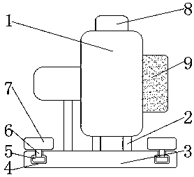
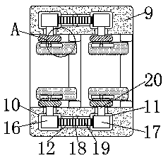
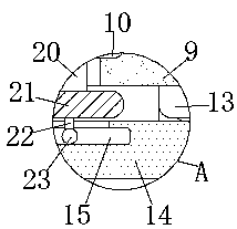
[0022] see Figure 1-3 , a high-efficiency and safe material conveying fan, including a fan body 1, a support frame 2 is fixedly connected to the lower surface of the fan body 1, a bottom plate 3 is fixedly connected to the bottom end of the support frame 2, and the support frame 2 plays a stable support for the fan body 1 The role of the fan body 1 is convenient for stable operation. The bottom plate 3 makes the fan body 1 stably placed on the ground. The in...


PUM


Abstract

The invention relates to the technical field of material conveying and discloses a high-efficiency safety material conveying fan. The high-efficiency safety material conveying fan comprises a fan body. The lower surface of the fan body is fixedly connected with a supporting frame. The bottom end of the supporting frame is fixedly connected with a bottom plate. The lower surface of the fan body isfixedly connected with a supporting frame. The bottom end of the supporting frame is fixedly connected with a bottom plate. The front surface of the bottom plate is provided with sliding grooves. Thetops of the inner walls of the sliding grooves are provided with ports. The ports communicate with the upper portion of the bottom plate. Sliding blocks are slidably connected to the interiors of thesliding grooves. The high-efficiency safety material conveying fan achieves the effect of changing the air flowing direction through air baffles when an air inlet pipe sucks external air. Gears achieve the effect of ensuring that the rotating direction of a first rotary ring and the rotating direction of a second rotary ring are opposite. Limiting balls move in limiting grooves to achieve the effect of changing deviation of the air baffles and promote the two air baffles to adjusting the air flowing direction. The effect of protecting air flow against vortexes is achieved. The air blowing efficiency of the fan body is improved.

Description

technical field [0001] The invention relates to the technical field of material conveying, in particular to an efficient and safe material conveying fan. Background technique [0002] The blower is also called a centrifugal fan. The centrifugal fan is a machine that relies on input mechanical energy to increase the gas pressure and discharge the gas. It is a driven fluid machine. Centrifugal fans are widely used in ventilation, dust removal and cooling of factories, mines, tunnels, cooling towers, vehicles, ships and buildings; ventilation and induction of boilers and industrial furnaces; cooling and cooling of air conditioning equipment and household appliances Ventilation; drying and selection of grain; wind tunnel wind source and inflation and propulsion of hovercraft, etc. [0003] When the fan sucks air from the outside, the airflow tends to form a vortex inside the intake pipe, and the vortex tends to backlog at the bend inside the fan, resulting in low efficiency of ...

Claims


Application Information

Patent Timeline
Patent Type & Authority Applications(China)
IPC IPC(8): B65G53/16
CPCB65G53/16
Inventor 徐洋袁逸如王蓉蓉
Owner ZHENJIANG DANTU DISTRICT FOOD FACTORY
Why Eureka
Try Eureka