
Valve base heat treatment device

A heat treatment device, heating device technology, applied in heat treatment furnaces, heat treatment equipment, furnaces, etc., can solve problems such as excessive temperature drop, and achieve the effect of energy saving

Inactive Publication Date: 2019-01-11
盐城市景盛石化机械有限公司
View PDF0 Cites 0 Cited by
  • Summary
  • Abstract
  • Description
  • Claims
  • Application Information

AI Technical Summary

Problems solved by technology

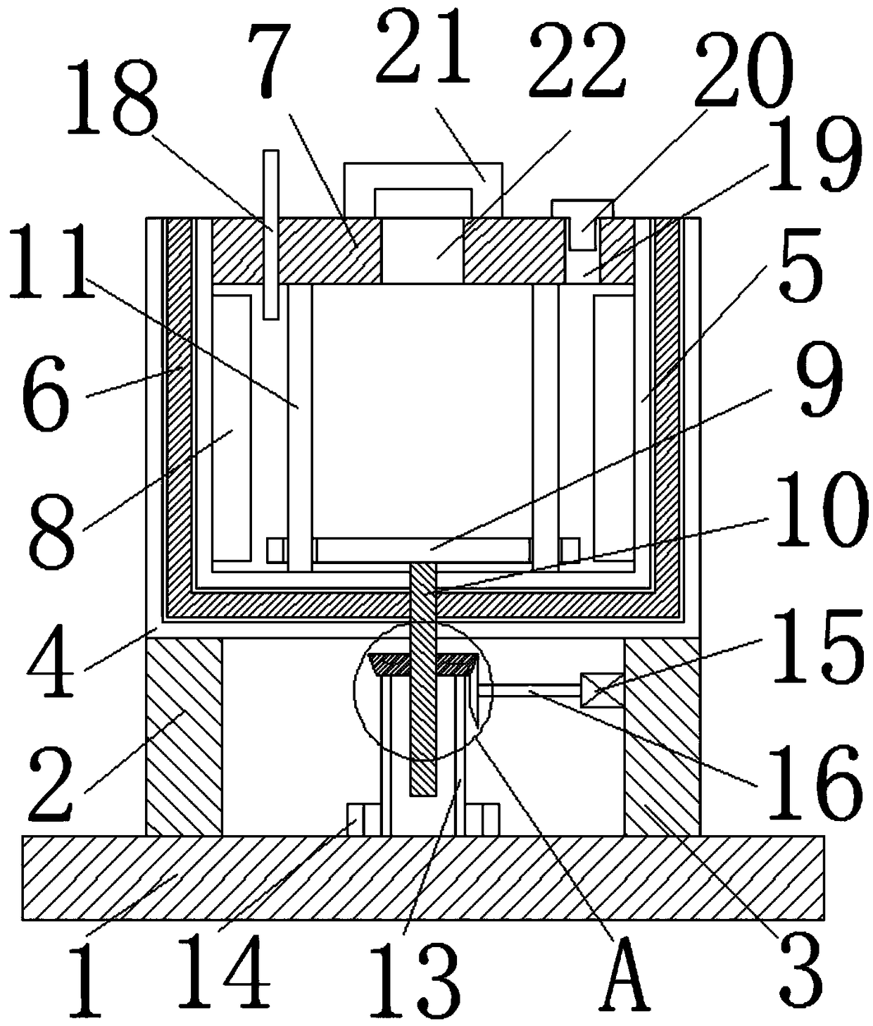
[0004] The purpose of the present invention is to solve the problem that the valve seat heat treatment device in the prior art is always in a heating state and the temperature drops too fast when it is not heated, and proposes a valve seat heat treatment device

Method used


Image

  • Valve base heat treatment device
  • Valve base heat treatment device

Examples


Embodiment Construction

[0019] The following will clearly and completely describe the technical solutions in the embodiments of the present invention with reference to the accompanying drawings in the embodiments of the present invention. Obviously, the described embodiments are only some, not all, embodiments of the present invention.

[0020] In describing the present invention, it should be understood that the terms "upper", "lower", "front", "rear", "left", "right", "top", "bottom", "inner", " The orientation or positional relationship indicated by "outside", etc. is based on the orientation or positional relationship shown in the drawings, and is only for the convenience of describing the present invention and simplifying the description, rather than indicating or implying that the referred device or element must have a specific orientation, so as to Specific orientation configurations and operations, therefore, are not to be construed as limitations on the invention.

[0021] refer to Figure ...


PUM


Abstract

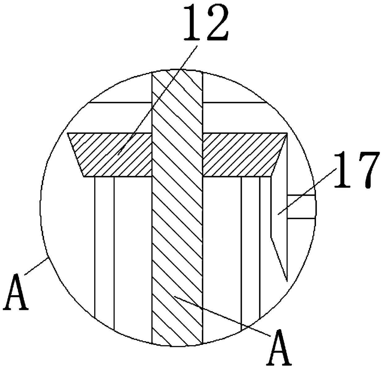
The invention discloses a valve base heat treatment device which comprises a base. A first supporting plate and a second supporting plate are connected to the upper surface of the base symmetrically and fixedly. The ends, away from the base, of the first supporting plate and the second supporting plate are connected with a heating box with an opening formed in the upper end together. The heating box comprises an outer shell and an inner shell. A heat preserving layer is fixedly installed between the inner shell and the outer shell. A box cover is hinged to one end, away from the box bottom, ofthe inner wall of the inner shell. A heating device is installed on the vertical inner wall of the inner shell symmetrically and fixedly. The heating device is located below the box cover. The valvebase heat treatment device reduces consumption of resources effectively, moreover, the situation that the temperature of the device is lowered too fast can be prevented effectively, heat can be preserved effectively, and the tempering effect of a valve base is better.

Description

technical field [0001] The invention relates to the technical field of valve seat heat treatment, in particular to a valve seat heat treatment device. Background technique [0002] Metal heat treatment is to heat a metal workpiece in a certain medium to a suitable temperature, and keep it at this temperature for a certain period of time, and then cool it in a different medium at different speeds, by changing the surface or internal microstructure of the metal material A process in which the structure is used to control its performance. Tempering is a kind of metal heat treatment, and tempering includes low temperature tempering, medium temperature tempering and high temperature tempering. Reheating the quenched workpiece to an appropriate temperature lower than the lower critical temperature Ac1 (the starting temperature of pearlite to austenite transformation during heating), and cooling in air, water, oil and other media after holding for a period of time. Metal heat trea...

Claims


Application Information

Patent Timeline
IPC IPC(8): C21D1/18C21D9/00
CPCC21D1/18C21D9/0068
Inventor 陈成
Owner 盐城市景盛石化机械有限公司
Learn More