Cloth printing and dyeing device

A technology for fabrics and dyes, applied in the field of fabric printing and dyeing devices, can solve the problems of inability to adjust the liquid level of the printing and dyeing pools.

Active Publication Date: 2019-01-11
罗茜
View PDF7 Cites 10 Cited by
  • Summary
  • Abstract
  • Description
  • Claims
  • Application Information

AI Technical Summary

Problems solved by technology

But this utility model can't adjust the liquid level height of printing and dyeing pool

Method used


Image

  • Cloth printing and dyeing device
  • Cloth printing and dyeing device
  • Cloth printing and dyeing device

Examples


specific Embodiment approach 1

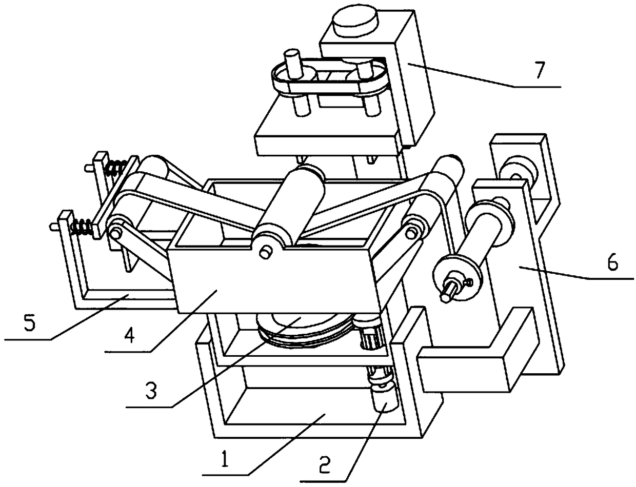
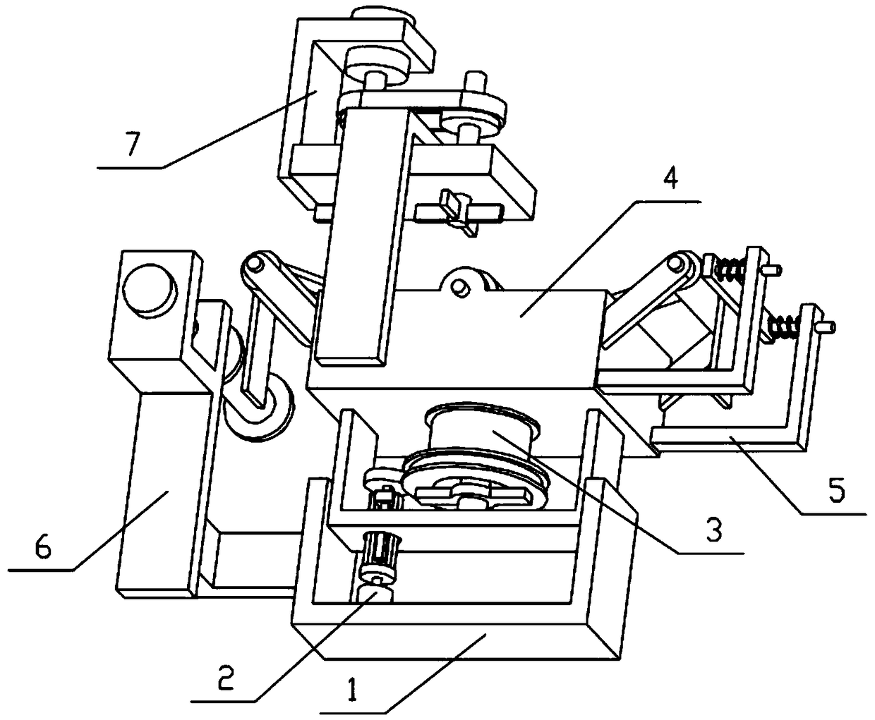
[0032] Combine below Figure 1-12 Describe this embodiment, the present invention relates to the field of printing and dyeing, more specifically a cloth printing and dyeing device, including a base 1, a driving assembly 2, a lifting cylinder 3, a dye container 4, a pressing assembly 5, a cloth receiving assembly 6 and a drying Component 7, the present invention can occupy the volume in the square box 4-1 through the lifting of the lifting cylinder 3. When the liquid level of the dye in the square box 4-1 is insufficient, the lifting cylinder 3 can be used to occupy the square box 4-1 The internal space makes the liquid level in the square box 4-1 rise, and it is not necessary to frequently add dyes with a suitable liquid level in the square box 4-1.

[0033] The driving assembly 2 is fixedly connected to the base 1, the lifting cylinder 3 is connected to the base 1 by threads, the driving assembly 2 is engaged with the lifting cylinder 3 for transmission, the dye container 4 i...

specific Embodiment approach 2

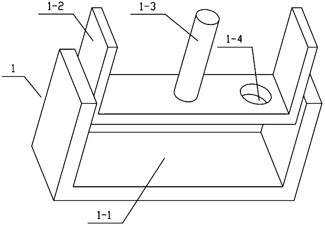
[0034] Combine below Figure 1-12Describe this embodiment, this embodiment will further explain Embodiment 1, the base 1 includes a door-shaped seat I1-1, a door-shaped seat II1-2, a threaded column 1-3 and a through hole 1-4, and the door-shaped seat I1 -1 and the door-shaped seat II1-2 are both in the shape of an inverted door, the door-shaped seat II1-2 is fixedly connected to the upper end of the door-shaped seat I1-1, and the threaded column 1-3 is fixedly connected to the middle position of the door-shaped seat II1-2 , the right side of the door-shaped seat II1-2 is provided with a through hole 1-4. Both the door-shaped seat I1-1 and the door-shaped seat II1-2 play a supporting role, and the function of the passing hole 1-4 is for the drive assembly 2 to pass through.

specific Embodiment approach 3

[0035] Combine below Figure 1-12 Describe this embodiment, this embodiment will further explain the second embodiment, the drive assembly 2 includes a motor I2-1, a disc 2-2, a connecting side column 2-3, a square column 2-4, a sliding sleeve 2- 5 and gear 2-6, the motor I2-1 is fixedly connected to the right side of the portal seat I1-1, the output shaft of the motor I2-1 is fixedly connected with the disc 2-2, and the upper end of the disc 2-2 is fixedly connected There are two connecting side columns 2-3, a sliding sleeve 2-5 is fixedly connected between the upper ends of the two connecting side columns 2-3, and a square column 2-4 is slidingly connected to the sliding sleeve 2-5, and the square column 2- The upper end of 4 is fixedly connected with gear 2-6, the output shaft of motor I2-1, disc 2-2 and gear 2-6 are coaxial, and the two connecting side columns 2-3 and square column 2-4 all pass through Holes 1-4. When the output shaft of the motor I2-1 rotates on its own...


PUM


Abstract

The invention relates to the field of printing and dyeing and particularly relates to a cloth printing and dyeing device. The device includes a base, a driving assembly, a lifting cylinder, a dye container, a compaction assembly, a cloth receiving assembly and an air drying device. The device is advantaged in that the volume of a square box can be occupied through lifting the lifting cylinder, when the dye level in the square box is not insufficient, the internal space of the square box can be occupied through lifting up the lifting cylinder, so the liquid level in the square box is raised, soadding the dye to the proper liquid level frequently to the square box is not needed. The driving assembly is fixedly connected with the base, the lifting cylinder is connected with the base throughthread, the driving assembly is in meshing transmission with the lifting cylinder, the dye container is fixedly connected with an upper end of the base, the lifting cylinder is in sliding connection with the dye container, the compaction assembly is fixedly connected with the left of the dye container, the cloth receiving assembly is fixedly connected with the right of the base, and the air dryingassembly is fixedly connected with an upper end of the dye container.

Description

technical field [0001] The invention relates to the field of printing and dyeing, in particular to a cloth printing and dyeing device. Background technique [0002] The application number is CN201720903127.3, a cloth printing and dyeing device. This utility model discloses a cloth printing and dyeing device, which includes a printing and dyeing room, a rinsing room and a dark dyeing solution storage tank. The bottom of the printing and dyeing room is fixedly connected with a supporting foot , one side of the top of the printing and dyeing room is provided with a water inlet, the other side of the top of the printing and dyeing room is connected to one end of the dye storage tank through a through pipe, and a first control valve is provided on one side of the through pipe, so The inside of the printing and dyeing room is clamped with an air charger, the inner bottom of the printing and dyeing room is provided with a heater, and one side of the printing and dyeing room is clam...

Claims


Application Information

Patent Timeline
Patent Type & Authority Applications(China)
IPC IPC(8): D06B3/10D06B23/20
CPCD06B3/10D06B23/20
Inventor 罗茜
Owner 罗茜
Why Eureka
Try Eureka