Aircraft floor slide track test device and application method

The technology of a test device and slide rail is applied in the direction of measuring device, application of stable tension/pressure test material strength, instruments, etc., which can solve the problems such as the lack of aircraft floor slide rail test devices and methods, and achieve strong practicability and eliminate Effect of torque influence

Pending Publication Date: 2019-01-11
上海秦耀航空试验技术有限公司
View PDF0 Cites 4 Cited by
  • Summary
  • Abstract
  • Description
  • Claims
  • Application Information

AI Technical Summary

Problems solved by technology

[0004] The purpose of the present invention is to provide a test device and a method of use used in the test of the bearing capacity of the aircraft floor slide rail or the structural strength verification test of the floor slide rail, so as to solve the problem that the existing aircraft floor slide rail test device and method are deficient

Method used


Image

  • Aircraft floor slide track test device and application method
  • Aircraft floor slide track test device and application method
  • Aircraft floor slide track test device and application method

Examples


Embodiment 1

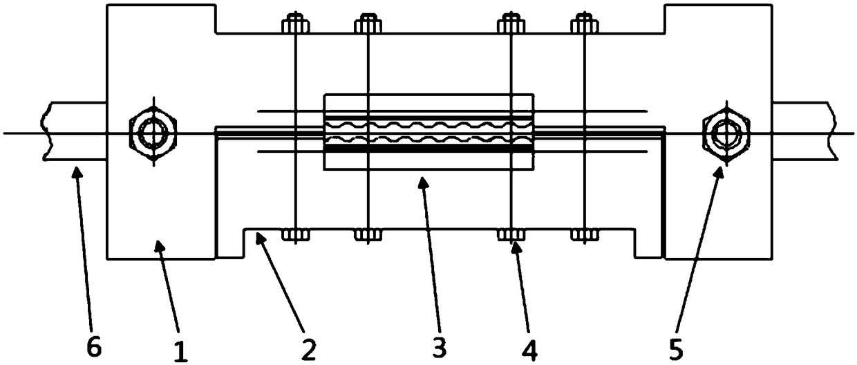
[0030] see Figure 1-8 , in an embodiment of the present invention, an aircraft floor slide rail test device includes a fixture A1 and a fixture B2, and the fixture A1 and the fixture B2 cooperate to clamp and fix the slide rail 3, and the bottom surfaces of the fixture A1 and the fixture B2 and the slide rail 3's inner edge contacts.

[0031] The clamping surface of the fixture A1 (the contact surface with the slide rail 3) is processed according to the shape modification of the web plate of the aircraft slide rail 3 and the inner edge of the slide rail 3, and a fastening bolt 4 passes through the hole A; the clamp B2 The clamping surface (the surface in contact with the slide rail 3) is modified and processed according to the shape of the aircraft slide rail 3 web and the inner edge of the slide rail 3, and a fastening bolt 4 passes through the hole B; the clamp A1 and the clamp B2 pass through The fastening bolts 4 are connected and fixed through the corresponding holes A ...

Embodiment 2

[0044] refer to Figure 9The difference between this embodiment and Embodiment 1 is that it also includes an actuator 9 for applying a vertical load to the loading joint 7, one end of the actuator 9 is hinged and fixed, and the other end of the actuator 9 passes through the sensor C15 is connected with the loading joint 7 to realize multi-directional combined loading on the basis of the original single-directional loading.

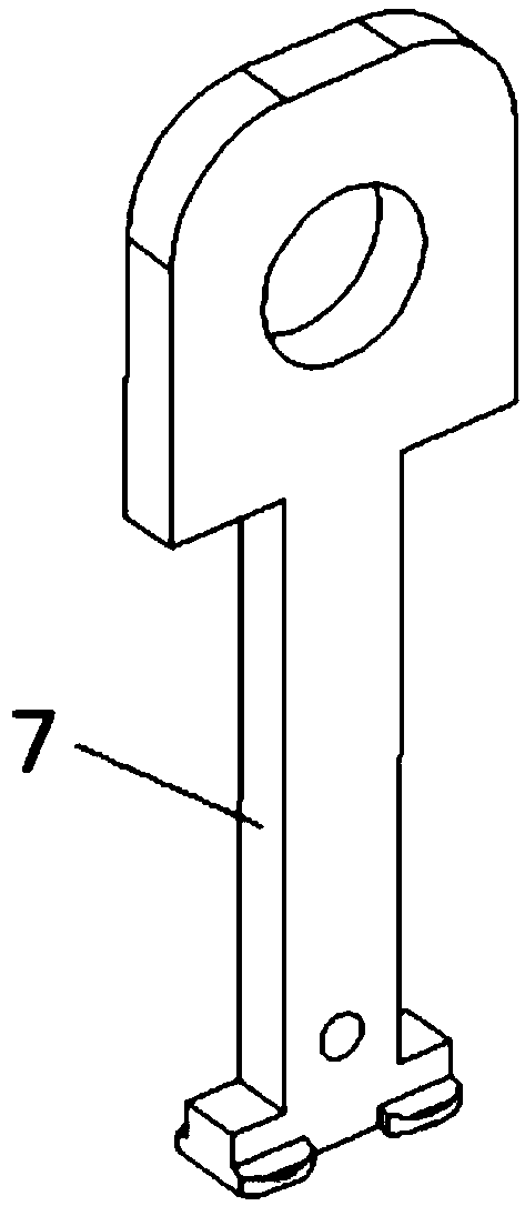
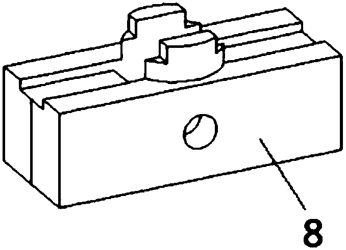
[0045] The aircraft floor slide rail test device has designed the aircraft slide rail 3 clamping structure, which is used to simulate the constraints of the aircraft floor slide rail 3 in actual use, and has designed a special loading joint 7, a ferrule 8 and an auxiliary loading structure for use in The aircraft slide rail 3 is actually loaded, and the equipment connection method and control strategy are proposed, which can realize the application of the test force while eliminating the influence of the moment, and can conveniently realize single-directio...


PUM


Abstract

The present invention discloses an aircraft floor slide track test device, comprises a clamp A and a clamp B, wherein the clamp A and the clamp B cooperatively fix the slide track, and the clamp A isalso fixedly connected to a floor rail groove through anchor bolts disposed at both ends of the clamp A; and further comprises a loading joint connected to the slide track; further comprises a ferruleconnected to the slide track for securing the loading joint; and further comprises two actuators on left and right side for applying a horizontal load to the loading joint. The invention also discloses a application method of an aircraft floor slide track test device. The method designs the aircraft floor slide track clamping structure for simulating constraints of an aircraft floor slide track in actual use, and designs the special loading joint, the ferrule and an auxiliary loading structure for applying the actual load of the aircraft slide track, and the device also proposes a connectionmethod and a control strategy to eliminate the influence of moment of force while applying test force, and to easily realize single-direction and multi-directional loading, and has strong practicability.

Description

technical field [0001] The invention relates to an aircraft floor slide rail test device and a use method, which are applied in research and development tests or strength verification tests of the aircraft floor slide rail bearing capacity. Background technique [0002] In the existing aircraft floor slide rail tests, there is a lack of devices and methods specifically for the test of the slide rail load-bearing capacity. The usual method is to perform mechanical calculations and assist with finite element analysis to determine the load-bearing capacity of the slide rails, and plan the seat connection statically. The force limit / ultimate load test is used to confirm the strength of related auxiliary structures including slide rails. The disadvantage of this strength assessment method is that it cannot accurately obtain the bearing capacity of the slide rail parts, and for the manufacturer, it is also impossible to obtain the manufacturing process parameters of the specific m...

Claims


Application Information

Patent Timeline
Patent Type & Authority Applications(China)
IPC IPC(8): G01N3/08
CPCG01N3/08G01N2203/0003G01N2203/0019G01N2203/025
Inventor 王海军朱林刚朱闯锋王高利
Owner 上海秦耀航空试验技术有限公司
Why Eureka
Try Eureka