Eureka AIR delivers breakthrough ideas for toughest innovation challenges, trusted by R&D personnel around the world.

A control circuit, a liquid crystal display drive module and a liquid crystal display device

A technology for controlling circuits and display modules, which is applied in the field of communication and can solve problems such as driver chip damage

Active Publication Date: 2019-01-11
VIVO MOBILE COMM CO LTD
View PDF8 Cites 3 Cited by
  • Summary
  • Abstract
  • Description
  • Claims
  • Application Information

AI Technical Summary

Problems solved by technology

[0004] The embodiment of the present invention provides a control circuit, a liquid crystal display drive module and a liquid crystal display device to solve the probability of damage to the drive chip under abnormal conditions big problem

Method used


Image

  • A control circuit, a liquid crystal display drive module and a liquid crystal display device
  • A control circuit, a liquid crystal display drive module and a liquid crystal display device
  • A control circuit, a liquid crystal display drive module and a liquid crystal display device

Examples


Embodiment Construction

[0017] The following will clearly and completely describe the technical solutions in the embodiments of the present invention with reference to the accompanying drawings in the embodiments of the present invention. Obviously, the described embodiments are some of the embodiments of the present invention, but not all of them. Based on the embodiments of the present invention, all other embodiments obtained by persons of ordinary skill in the art without creative efforts fall within the protection scope of the present invention.

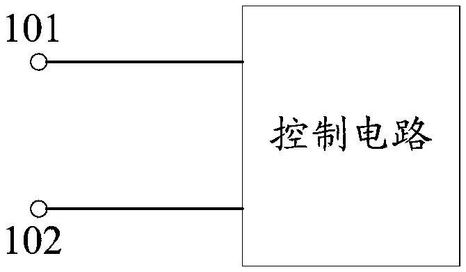
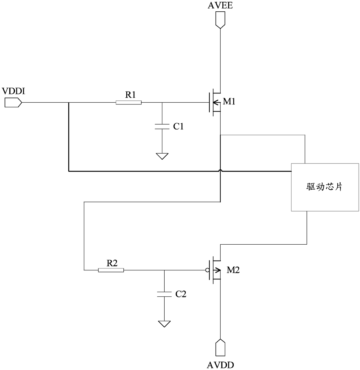
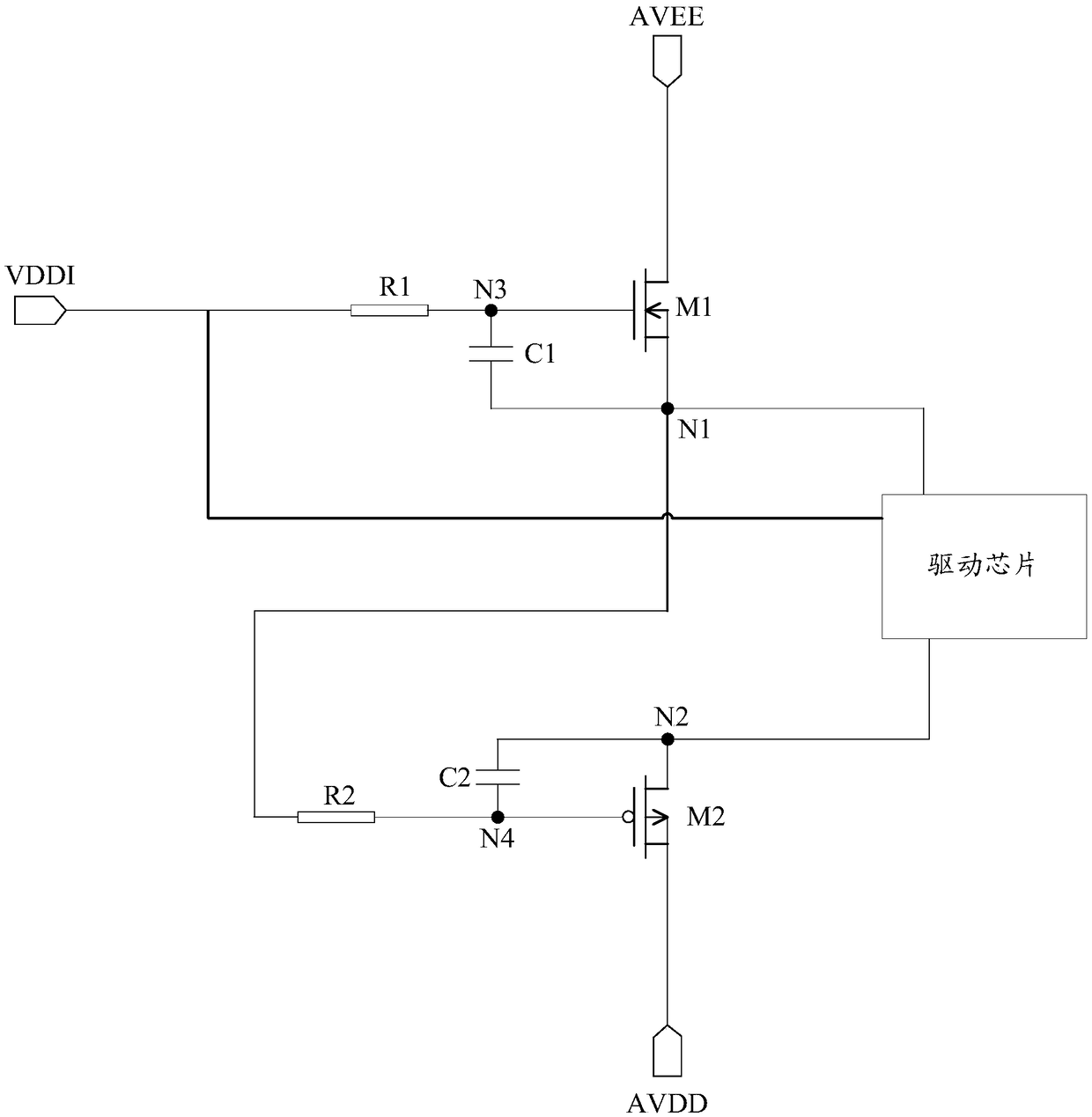
[0018] see figure 1 , figure 1 It is a schematic structural diagram of a control circuit provided by an embodiment of the present invention, and the control circuit is used to control the on-off timing of multiple external power supply signals input to the driver chip of the display module, such as figure 1 As shown, the control circuit includes a first input terminal 101 and a second input terminal 102 respectively receiving different external power ...


PUM


Abstract

A control circuit, a liquid crystal display drive module and a liquid crystal display device are provided. The control circuit comprises a first input terminal and a second input terminal which respectively receive different external power signals, the control circuit sequentially controls the first input terminal, the second input terminal inputs power signals to the driving chip, and sequentially controls the second input terminal, and the first input terminal is powered down. In this way, by controlling the normal timing of different power supply signals, the probability of damage to the drive chip can be reduced.

Description

technical field [0001] The invention relates to the technical field of communication, in particular to a control circuit, a liquid crystal display drive module and a liquid crystal display device. Background technique [0002] With the rapid development of liquid crystal display technology, liquid crystal display devices have become common in people's lives, and have brought new visual experiences to users. The external power supply of the driver chip of the LCD driver module mainly includes VDDI signal, AVDD signal and AVEE signal. Under normal circumstances, the VDDI signal is powered on before the AVDD signal and AVEE signal, and the VDDI signal is powered off after the AVDD signal and AVEE signal. , the three work together to make the LCD driver module work normally. [0003] However, under abnormal circumstances, the AVDD signal and AVEE signal may be powered on before the VDDI signal, or the AVDD signal and AVEE signal may be powered off after the VDDI signal, which m...

Claims


Application Information

Patent Timeline
IPC IPC(8): G09G3/36
CPCG09G3/36H03K17/296G09G3/3696G09G2330/026G09G2330/027G09G2330/028G09G2330/04G09G2310/066G09G2330/025G06F1/266G09G2330/02G09G2300/0426
Inventor 文亮
Owner VIVO MOBILE COMM CO LTD
Why Eureka
Eureka Blog
Learn More