Loop inductance winding machine

A toroidal inductor and winding machine technology, applied in coil manufacturing and other directions, can solve the problems of low winding efficiency, low winding quality, and uneven wiring.

Pending Publication Date: 2019-01-11
陈荣亚
View PDF0 Cites 1 Cited by
  • Summary
  • Abstract
  • Description
  • Claims
  • Application Information

AI Technical Summary

Problems solved by technology

[0004] The purpose of the present invention is to provide a ring-shaped inductance winding machine to solve the technical problems of low winding efficiency, uneven wire arrangement and low winding quality of the inductance winding machine above 0.8MM in the prior art

Method used


Image

  • Loop inductance winding machine
  • Loop inductance winding machine
  • Loop inductance winding machine

Examples


Embodiment 1

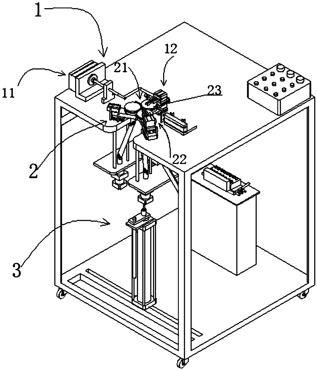
[0046] figure 1 A structural schematic diagram of a ring-shaped inductor winding machine provided in an embodiment of the present invention at a viewing angle, figure 2 A structural schematic diagram of a ring-shaped inductor winding machine provided in an embodiment of the present invention at a viewing angle, image 3 For a schematic view of the structure of the ring-shaped inductor winding machine provided by the embodiment of the present invention, please refer to Figure 1-3 As shown, the annular inductance winding machine of this embodiment includes a frame and a wire turning mechanism 1, a wire arranging mechanism 2 and a hooking mechanism 3 arranged on the frame. The annular inductance winding machine of this embodiment winds the copper wire on the magnetic ring.

[0047]The thread turning mechanism 1 includes a first driving structure 11 and a first clamping structure 12 connected to the first driving structure 11; in this embodiment, the first driving structure 11...

Embodiment 2

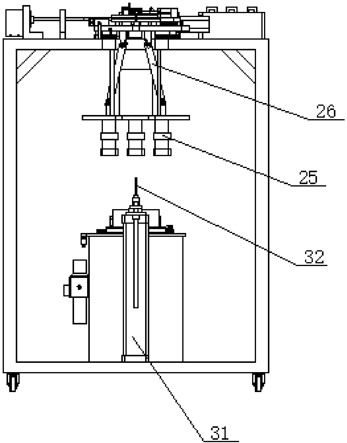
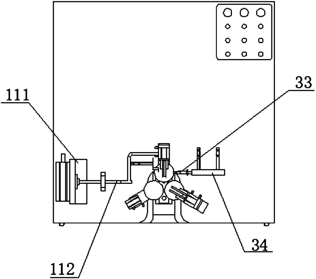
[0054] Figure 4 A structural schematic diagram of a ring-shaped inductor winding machine provided in an embodiment of the present invention at a viewing angle, Figure 5 For a schematic view of the structure of the ring-shaped inductor winding machine provided by the embodiment of the present invention, please refer to Figure 3-5 As shown, this embodiment has an overall structure similar to that of Embodiment 1, the difference is that this embodiment provides a specific structure of a ring-shaped inductor winding machine on the basis of Embodiment 1.

[0055] In this embodiment, the first clamping structure 12 includes a first finger cylinder for clamping the inductor wire, and a fifth driving structure for driving the first finger cylinder, and the second clamping structure 22 includes The second finger cylinder for clamping the inductance wire is used to drive the sixth drive structure of the second finger cylinder. The first drive structure 11 includes a rotary cylinder ...


PUM


Abstract

A loop inductance winding machine comprises a rack and a thread turning mechanism arranged on the rack, a line arrangement mechanism and a hook mechanism, a line tur mechanism includes a first drive structure, a first clamping structure connected to the first drive structure, a line arrange mechanism includes a magnetic re frame and a second clamping structure, the magnetic ring frame comprises atleast three clamping rollers arranged in a circumferential direction, a second drive structure that drives each of the pinch rollers to rotate, a third driving structure for driving the clamping coilof the clamping roller, wherein each clamping roller is correspondingly connected with the second driving structure through a coupling, the second clamping structure is used for clamping the inductive wire, and the hook mechanism comprises a fourth driving structure, a winding hook, a push rod and a push rod driving structure connected with the fourth driving structure. The ring inductance winding machine realizes winding of the magnetic loop through the wire turning mechanism, the wire arranging mechanism and the hook wire mechanism, and reduces the winding strength and improves the windingefficiency.

Description

technical field [0001] The invention relates to the technical field of winding machines, in particular to a ring-shaped inductor winding machine. Background technique [0002] With the development of the economy and the progress of the times, there are more and more electrical products, and there are more and more corresponding electronic components. As a kind of electronic components, ring inductors play an important role in electrical appliances. . [0003] The usual toroidal inductance is made by manual winding, the appearance shape is very random, it is difficult to wind into a uniform shape, in this case, the production efficiency and quality of the toroidal inductance are greatly affected. The machine can only wind inductance with a wire diameter below 0.8MM. The inductance winding machine above 0.8MM generally adopts the combination of cylinder and crochet, and uses the movement of the cylinder to replace the hook pulling action of the human hand. Although this metho...

Claims


Application Information

Patent Timeline
Patent Type & Authority Applications(China)
IPC IPC(8): H01F41/08
CPCH01F41/08
Inventor 陈荣亚
Owner 陈荣亚
Why Eureka
Try Eureka