A needle guide for venipuncture and a puncture kit

A technique for venipuncture and needle guide, applied in the field of medical devices, can solve the problems of puncture failure, changing the needle insertion direction, and difficulty in ensuring the adjustment device, etc., and achieves the effects of high puncture success rate, improved work efficiency, and strong stability.

Pending Publication Date: 2019-01-15
XIANGYA HOSPITAL CENT SOUTH UNIV
View PDF1 Cites 2 Cited by
  • Summary
  • Abstract
  • Description
  • Claims
  • Application Information

AI Technical Summary

Problems solved by technology

These needle guides are independent, and are usually selected by nurses after judging the distance between the ultrasound probe and subcutaneous blood vessels under B-ultrasound. Sometimes the exact depth cannot be judged, or for other depths such as 0.5cm, 0.6cm, etc. from the skin surface The blood vessels cannot be accurately punctured, resulting in puncture failure
[0003] Chinese patent specification CN205672311U discloses a multi-angle needle guide for venipuncture. Although the needle guide can adjust the angle of needle insertion during puncture, its adjustment device is only fixed to the connecting block by a bolt. In general, the needle insertion direction of the puncture needle is adjusted by making the puncture needle follow the adjustment device to rotate around the fixed shaft. Obviously, only through one point of fixation, the adjustment device is easy to shift when the needle is actually inserted, changing the needle insertion direction, resulting in puncture fail
Moreover, when adjusting the adjusting device to a certain angle, when tightening the bolt to fix the adjusting device at this position, the operator needs to maintain the existing position of the adjusting device with one hand and tighten the bolt with the other hand, so it is difficult to ensure that the adjusting device is always kept at the target angle , causing the final puncture direction to be inconsistent with the target direction

Method used


Image

  • A needle guide for venipuncture and a puncture kit
  • A needle guide for venipuncture and a puncture kit
  • A needle guide for venipuncture and a puncture kit

Examples


Embodiment Construction

[0037] The following will refer to the accompanying drawings Figure 1 to Figure 12 The present invention will be described in detail in combination with examples. It should be noted that, in the case of no conflict, the embodiments of the present invention and the features in the embodiments can be combined with each other. For the convenience of description, if the words "up", "down", "left" and "right" appear in the following, it only means that the directions of up, down, left and right are consistent with the drawings themselves, and do not limit the structure.

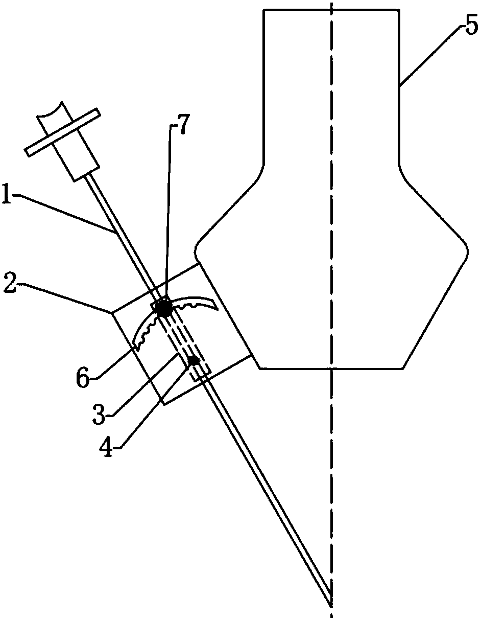
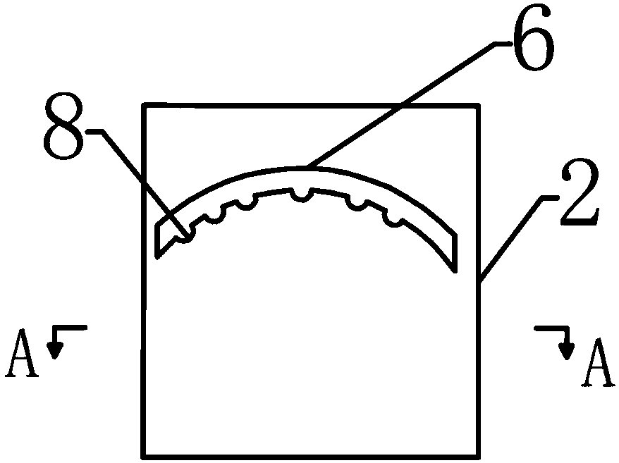
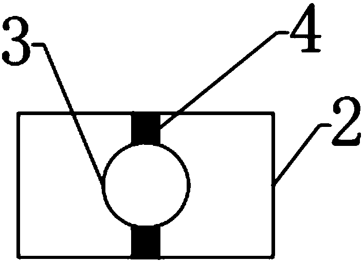
[0038] figure 1 It is a structural schematic diagram of the use state of the needle guide for venipuncture in this embodiment, and the needle guide has been fixed on the ultrasonic probe 5 . The needle guide includes a body 2, in which is provided a limiting tube 3 for accommodating the puncture needle 1, one end of the limiting tube 3 is rotatably connected to the inner wall of the body 2, and the outer wall o...


PUM


Abstract

The invention relates to a needle guide for venipuncture. The needle guide comprises a main body, wherein a limiting tube for accommodating the puncture needle is arranged in the main body, one end ofthe limiting tube is rotatably connected with the inner wall of the main body, a clamping slot which is consistent with the length direction of the limiting tube is arranged on the outer wall of thelimiting tube, and a limiting rod which can move along the length direction of the clamping slot is arranged in the clamping slot; the main body is provided with an arc-shaped groove, the limiting rodextends outwardly out of the clamping groove and protrudes to the outer body through the arc-shaped groove, and the lower edge of the arc-shaped groove is provided with a plurality of grooves which can accommodate the limiting rod; the upper top surface and the lower bottom surface of the main body are provided with openings for the puncture needle to move. The needle guide has the advantages ofconvenient use, adjustable needle feeding angle and strong stability, and can effectively improve the puncture success rate, improve the working efficiency of medical personnel and reduce the pain ofpatients.

Description

technical field [0001] The invention belongs to the field of medical devices, in particular to a needle guide for venipuncture and a puncture set. Background technique [0002] B-ultrasound-guided puncture can detect the position and direction of blood vessels, and can see subcutaneous blood vessels. You can choose non-obvious supracubital veins, increase the freedom of movement and comfort of the catheterizing arm, and reduce catheterization complications. Needle guides are generally needed for puncture. Currently, there are only three types of needle guides on the market: 1cm, 1.5cm, and 2cm. These needle guides are independent, and are usually selected by nurses after judging the distance between the ultrasound probe and subcutaneous blood vessels under B-ultrasound. Sometimes the exact depth cannot be judged, or for other depths such as 0.5cm, 0.6cm, etc. from the skin surface The blood vessels cannot be accurately punctured, resulting in puncture failure. [0003] Chi...

Claims


Application Information

Patent Timeline
Patent Type & Authority Applications(China)
IPC IPC(8): A61B17/34A61M5/42
CPCA61B17/3403A61B2017/3413A61M5/427
Inventor 刘万里贺连香
Owner XIANGYA HOSPITAL CENT SOUTH UNIV
Why Eureka
Try Eureka