Water spout structure

A water nozzle and water flow technology, applied in the direction of spraying device, spraying device, etc., can solve the problems of large volume, inability to form effective water column, etc., achieve simple structure, good water spraying effect, and reduce the probability of water leakage Effect

Pending Publication Date: 2019-01-15
ZHEJIANG UISH ENVIRONMENT TECH CO LTD
View PDF0 Cites 0 Cited by
  • Summary
  • Abstract
  • Description
  • Claims
  • Application Information

AI Technical Summary

Problems solved by technology

[0002] At present, the showers and similar water spray structures that we generally use have certain requirements for water pressure, otherwise, the effective water column cannot be formed after the water is sprayed, or the water column cannot be formed. In addition, most of the water spray structures only spray water in one direction and the volume larger

Method used


Image

  • Water spout structure
  • Water spout structure
  • Water spout structure

Examples


Embodiment 1

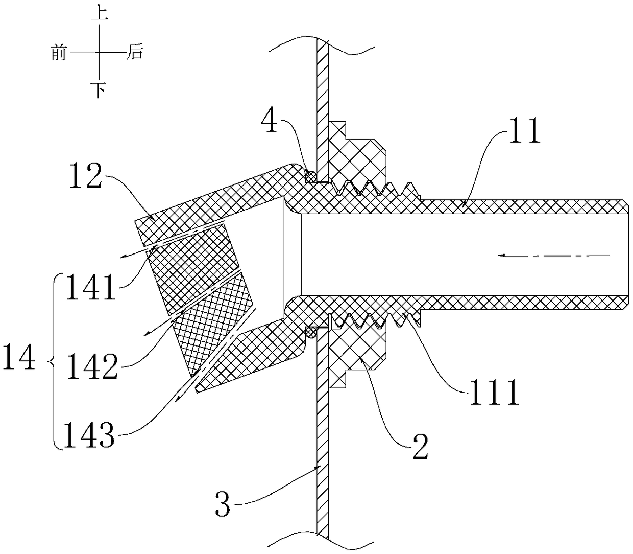
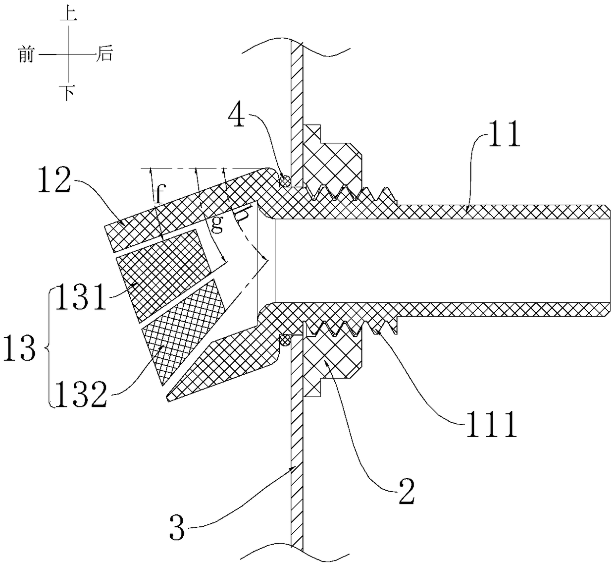
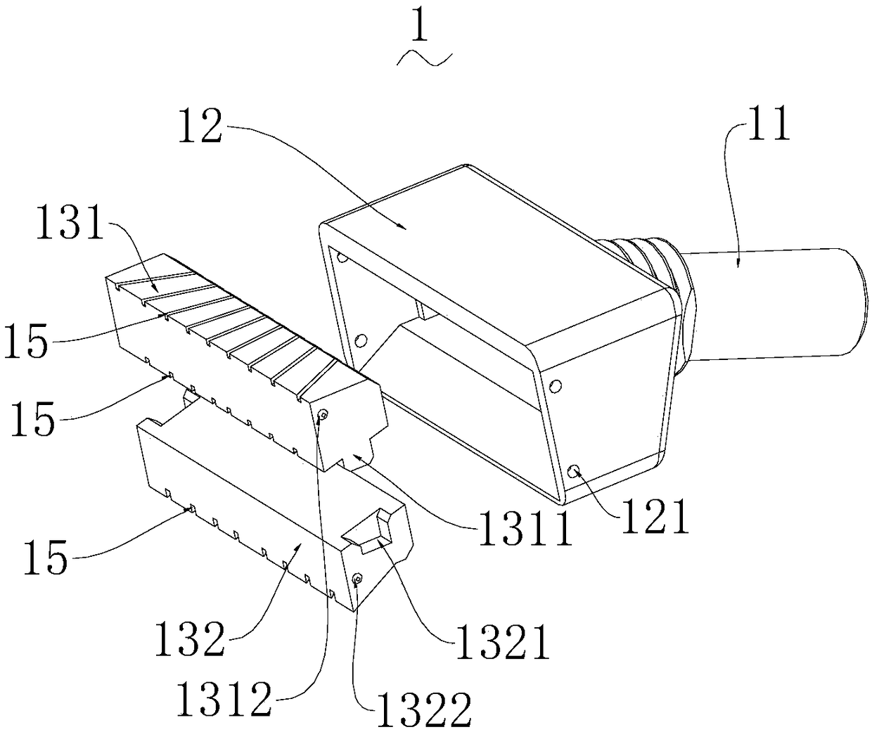
[0039] see Figure 1 to Figure 3 shown, which are respectively the schematic cross-sections of the water nozzle structure of the present invention Figure 1 , cross section Figure II And the explosion diagram of the water nozzle body.

[0040] to combine Figure 1 to Figure 3 As shown, a water nozzle structure includes a water nozzle body 1, and the water nozzle body 1 includes a water inlet portion 11 and a water outlet portion 12 that communicate with each other, and a plurality of flow dividers 13 are arranged in the water flow portion 12, and the flow divider 13 Separate multiple layers of water flow channels 14, there is an angle between any two layers of water flow channels 14, each layer of water flow channels 14 includes a plurality of water flow holes 15, when in use, water flows in from the water inlet 11 and is sprayed out from the water flow holes 15, form a column of water. In this embodiment, there is an included angle between any two water flow holes 15 on ...

Embodiment 2

[0045] As with the water nozzle structure described in Embodiment 1, the difference of this embodiment is that the cross-sectional area of ​​the water inlet part 11 is j, and the sum of the cross-sectional areas of all water flow holes 15 is k, where j / k>5, when If the ratio of j / k is too small, a larger water inlet pressure will be required to form a water column in the nozzle structure, which will affect the user's experience of use, and the requirements for the use scene of the nozzle structure will also be increased.

[0046] In this embodiment, it is preferred that j / k=6, which can not only ensure the formation of the water column, but also ensure a certain amount of water, so that the user experience is the best.

[0047] In the water nozzle structure of the present invention, the relationship between the cross-sectional area of ​​the water flow hole and the cross-sectional area of ​​the water inlet is designed to ensure that the water nozzle structure can still form a wa...

Embodiment 3

[0049] The water nozzle structure as described in the second embodiment, the difference of this embodiment is that, as figure 1 As shown, the multi-layer water flow channels 14 are arranged sequentially from top to bottom, and the water outlet end of each layer of water flow channels 14 has a distance from the water inlet part 11, and the distance decreases successively from top to bottom, so that the entire front end of the water outlet part 12 faces down slope.

[0050] The nozzle structure in the present invention is provided with the relative position of the water outlet part 12 and the water inlet part 11, that is, the position of the water outlet end of the multi-layer water flow channel 14 is arranged close to the water inlet part 11 successively from top to bottom, so that each layer is sprayed out. The difference in the horizontal distance of the water column is more obvious, which improves the spraying effect of the nozzle structure.


PUM


Abstract

The invention provides a water spout structure, comprising a water spout body, which includes a water inlet portion and a water outlet portion that penetrate each other, wherein the water inlet portion and the water outlet portion are integrally formed. A plurality of flow dividers are disposed in the water outlet portion, and the flow dividers separates the water outlet portion into a plurality of water flow channels. An included angle is formed between any two water flow channels. Each of the water flow channels includes a plurality of water flow holes. In use, water flows in from the waterinlet portion and is ejected from the water flow holes to form a water column. In the water spout structure, water flow channels are separated by flow dividers. Each layer of water flow channel will also be diverted through the water flow hole to divert the water to all directions and angles. The water spraying effect is good, the structure is simple, and the use is very convenient. The structureis simple, the installation steps are saved, and the probability of water leakage of a water spout body is reduced.

Description

technical field [0001] The invention relates to the technical field of shower structures, in particular to a water nozzle structure. Background technique [0002] At present, the showers and similar water spray structures that we generally use have certain requirements for water pressure, otherwise, the effective water column cannot be formed or the water column cannot be formed after the water is sprayed out. In addition, most of the water spray structures only spray water in one direction and the volume larger. [0003] In view of the above-mentioned deficiencies, the creator of the present invention has finally obtained the present invention through long-term research and practice. Contents of the invention [0004] In order to solve at least one aspect of the above problems, the technical solution adopted by the present invention is to provide a water nozzle structure, including a water nozzle body, and the water nozzle body includes a water inlet part and a water out...

Claims


Application Information

Patent Timeline
Patent Type & Authority Applications(China)
IPC IPC(8): B05B1/04
CPCB05B1/04
Inventor 叶秀友任士水强建东沈立强
Owner ZHEJIANG UISH ENVIRONMENT TECH CO LTD
Why Eureka
Try Eureka