
Construction device for energy-saving building and working method thereof

A construction device and construction technology, which is applied to the construction device of energy-saving buildings and the application field of the construction device, can solve the problems of affecting the bending quality, uneven stress on the steel bar, affecting the bending efficiency of the steel bar, etc., so as to improve the bending efficiency and ensure the Bending quality, the effect of saving bending time

Active Publication Date: 2019-01-15
国家电投集团江西中业兴达电力实业有限公司
View PDF6 Cites 2 Cited by
  • Summary
  • Abstract
  • Description
  • Claims
  • Application Information

AI Technical Summary

Problems solved by technology

[0003] At present, the trolley on the workbench is fixed on the rear by bolts and cooperates with the central pin shaft to bend the steel bar. When it is necessary to bend the steel bar specifications with different diameters, it is necessary to manually adjust the trolley to a suitable position and then fix it. Bending steel bars with different diameters affects the bending efficiency of the steel bars, and the steel bars to be bent are placed directly between the bending pin and the center pin, which is easy to cause deviation due to uneven stress on the steel bars during the bending process , affecting the bending quality

Method used


Image

  • Construction device for energy-saving building and working method thereof
  • Construction device for energy-saving building and working method thereof
  • Construction device for energy-saving building and working method thereof

Examples


Embodiment Construction

[0038] The technical solutions of the present invention will be clearly and completely described below in conjunction with the embodiments. Apparently, the described embodiments are only some of the embodiments of the present invention, not all of them. Based on the embodiments of the present invention, all other embodiments obtained by persons of ordinary skill in the art without creative efforts fall within the protection scope of the present invention.

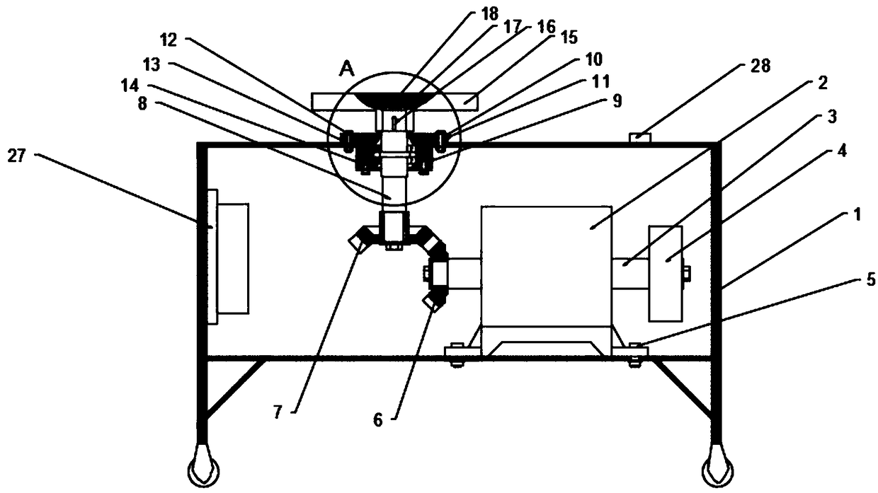
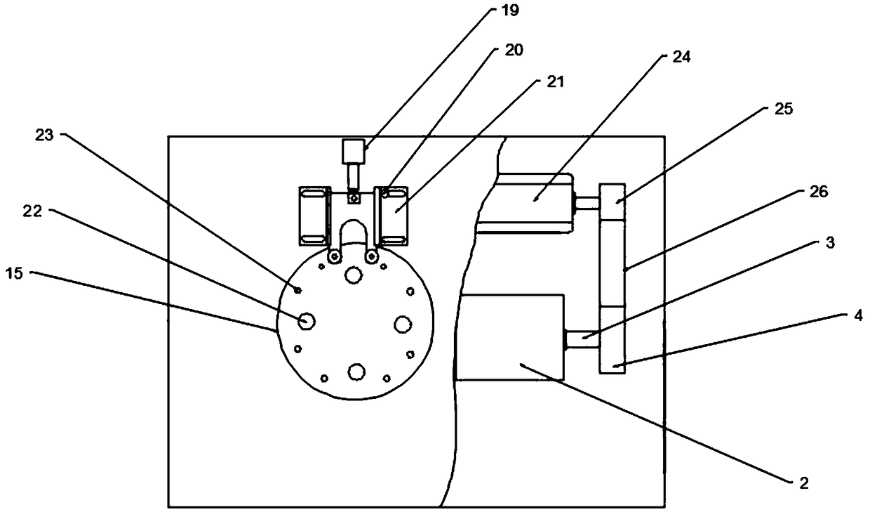
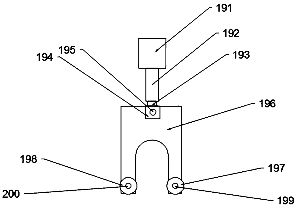
[0039] See Figure 1-7 , a construction device for an energy-saving building, comprising a housing 1, the interior of the housing 1 is a hollow structure, a reduction box 2 is fixed on the right inner wall of the housing 1 through a first fixing bolt 5, and the right end of the reduction box 2 is provided with a The connecting shaft 3, the right end of the connecting shaft 3 is fixedly connected with the driven wheel 4, the left end of the reduction box 2 is provided with an output shaft, the left end of the output shaft is...


PUM


Abstract

The invention discloses a construction device for an energy-saving building. The construction device for the energy-saving building comprises a shell, and the interior of the shell is of a hollow structure. A reduction box is fixed to the inner wall of the right side of the shell through a first fixing bolt, and a transmission shaft penetrates through the top end of the shell. A working table is arranged at the upper end of the transmission shaft, and the working table is provided with a plurality of central pin shafts at equal intervals in the circumferential direction. The central pin shaftsare detachably installed on the upper surface of the working table, and supporting pin shafts are arranged at the front ends of the central pin shafts in a left-right symmetric mode. A bending mechanism is arranged in front of the working table. The depths and heights of stepped structures on a first bent pin shaft, a second bent pin shaft, the central pin shafts and the supporting pin shafts areset to be the same, steel bars do not offset during bending, the supporting pin shafts with different diameters and specifications are arranged on the working table, so that manual replacement of thesupporting pin shafts are not required during bending, the bending time can be greatly saved, the bending efficiency is improved, and the bending quality of the steel bars is effectively ensured.

Description

technical field [0001] The invention relates to a construction device, in particular to a construction device for an energy-saving building, and belongs to the technical field of construction device application. Background technique [0002] Building construction refers to the production activities in the implementation stage of engineering construction. It is the construction process of various buildings. It can also be said to be the process of turning various lines on the design drawings into real objects at designated locations. It includes basic engineering construction, main structure construction, roofing engineering construction, decoration engineering construction, etc. The place of construction work is called "building construction site" or "construction site". Building construction is carried out by people using various building materials and mechanical equipment in a certain space and time according to a specific design blueprint. Production activities for const...

Claims


Application Information

Patent Timeline
Patent Type & Authority Applications(China)
IPC IPC(8): B21F1/00
CPCB21F1/00
Inventor 俞美英
Owner 国家电投集团江西中业兴达电力实业有限公司
Learn More