Hammer rod mechanism of sub-transmission direct-drive four-hammerhead precision forging machine

A four-hammer, precision forging machine technology, applied to hammers, hammer driving devices, forging/pressing/hammer devices, etc., can solve the problems of difficult manufacturing, many processing elements, inconvenient maintenance, etc. Simple and convenient, simple and reliable transmission system, avoid the effect of transmission connection

Pending Publication Date: 2019-01-15
沈阳重机重矿机械设备制造有限公司
View PDF2 Cites 2 Cited by
  • Summary
  • Abstract
  • Description
  • Claims
  • Application Information

AI Technical Summary

Problems solved by technology

However, the structure of the hammer rod mechanism of this type of precision forging machine is complicated, there are many processing elements, high precision requirements, difficult manufacturing, long processing cycle, high cost and inconvenient maintenance, and the connection structure between the hammer rod mechanism and the main drive motor is complicated. many parts
The utility model with the application number CN89210704.9 discloses a "four-hammer radial forging machine", which includes 4 sets of unit forging boxes arranged diagonally, the corresponding hammerhead drive system and the radial feed mechanism , this utility model improves the structure of the double-slider sinusoidal mechanism of the GMF precision forging machine, but it adopts a combined frame, and the 4 sets of striking mechanisms are respectively installed in 4 independent unit forging boxes, and each unit forging box is composed of a box body , eccentric shaft, horizontal slider, main slider and flywheel. Each unit forging box is equipped with a gear package. Inside the box of the unit forging box, there is a double-slider sinusoidal mechanism that drives the hammer head to strike. The horizontal slider It is divided into two pieces and respectively embedded on both sides of the main slider. The eccentric shaft in the unit forging box is equipped with a flywheel at one end and a balance wheel at the other end, and there are counterweights on the flywheel and the balance wheel; especially, the The utility model adopts the motor to drive the shaft S through the pulley 1 , and then drives the shaft S through the bevel gear set 3 Rotation is also connected with a feather key and a universal shaft joint to ensure the synchronous rotation of the four eccentric shafts. Therefore, the structure of the utility model is relatively complicated;
[0003] The second type is the hydraulic type, such as the fully hydraulic precision forging machine of SMS Meer in Germany. This type of precision forging machine can achieve large tonnage pressure, but it is only suitable for large machines, and the hydraulic control system is complicated, and there is a hidden danger of liquid leakage. , especially if the frequency cannot be reached very high, the highest can only reach 300 times / min, which is not suitable for manufacturing small precision forging machines
In the invention, the workpiece size adjustment oil cylinder is fixedly connected to the machine frame. The workpiece size adjustment oil cylinder is equipped with an inner piston and an outer piston, the inner piston is fixedly connected with the connecting rod, and the outer piston is fixedly connected with the hammer rod and the hammer head. The drive motors are all servo motors. The advantage of the present invention is that there is no need to arrange an eccentric sleeve and a mechanical adjustment mechanism, so the structure is simple. However, each group of striking mechanisms in this invention is composed of a drive motor, a pinion with external teeth, Composed of flywheel, eccentric shaft, connecting rod, hammer rod, hammer head, workpiece size adjustment cylinder, inner piston, outer piston, etc., the pinion with external teeth and the moving motor are fixedly connected with the pinion with external teeth and the pinion with external teeth The flywheel meshes, the workpiece size adjustment oil cylinder is fixedly connected with the frame, and the inner piston and outer piston are slidingly connected with the workpiece size adjustment oil cylinder. It can be seen that the motor in the mechanical transmission system of the invention also needs to transmit power to the main shaft through the gear box, and at the same time , the invention adjusts the position of the hammer head through the workpiece size adjustment cylinder, the structure is complex, the precision is low and the stability is poor

Method used


Image

  • Hammer rod mechanism of sub-transmission direct-drive four-hammerhead precision forging machine
  • Hammer rod mechanism of sub-transmission direct-drive four-hammerhead precision forging machine
  • Hammer rod mechanism of sub-transmission direct-drive four-hammerhead precision forging machine

Examples


Embodiment Construction

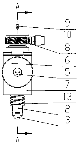
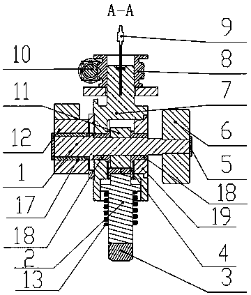
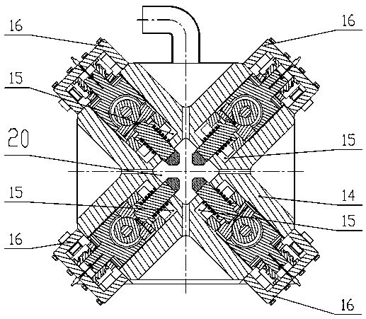
[0028] like figure 1 and figure 2 As shown, the technical solution adopted by the present invention includes a main shaft 1, a hammer shaft 2 and a hammer head 3. The main shaft 1 is a four-stage stepped shaft, and from left to right are respectively the first cylindrical section, the second cylindrical section, and the third cylindrical section. The cylinder section and the fourth cylinder section are also provided with an expansion sleeve positioning shoulder between the first cylinder section and the second cylinder section, and an expansion sleeve 17 is installed on the first cylinder section of the main shaft 1, and the expansion sleeve 17 makes the The main shaft 1 is directly connected with the motor 12. The motor 12 is a hollow servo motor. An eccentric wheel 11 is installed on the second cylindrical section of the main shaft 1. A shaft sleeve 18 is installed on the left and right sides of the eccentric wheel 11. On the left side of the shaft sleeve 18 Sliding suppor...


PUM


Abstract

The invention discloses a hammer rod mechanism of a sub-transmission direct-drive four-hammerhead precision forging machine, aiming to overcome the defects that an existing mechanical transmission precision forging machine is complex in structure, large in manufacturing difficulty, high in cost, inconvenient to maintain, and a hydraulic type precision forging machine is complex in structure, poorin stability and low in frequency, is not suitable for manufacturing a small precision forging machine. The hammer rod mechanism is characterized in that a motor is installed on the main shaft, the motor is directly connected with the main shaft, the motor is a hollow servo motor, and the upper end of the sliding support is in threaded connection with a press-down worm wheel, the press-down worm wheel is connected with a worm, a position sensor is further inserted at the upper end of the sliding support, and when the hollow servo motor rotates, an eccentric wheel is driven to rotate, the hammer rod sliding block is pressed down, the one-time impact of the hammer heads is completed, and when the hammer heads return, the hammer heads and the hammer rod sliding block are in linkage rising bythe hammer head return spring, and the hammer heads reciprocate once as the motor rotates a cycle. The main transmission mechanism is simple, a large number of transmission connecting pieces are avoided, and installation and maintenance are easy and convenient, so that the consumption and replacement of the large number of transmission connecting pieces are avoided.

Description

technical field [0001] The invention belongs to the technical field of forging machinery, in particular to a hammer rod mechanism of a split-drive direct-drive four-hammer precision forging machine. Background technique [0002] There are two types of four-hammer precision forging machines in the prior art. The first type is mechanical transmission, which is transmitted to the 4 hammer rods by one or two motors through a gear set, such as the precision forging machine of GFM Company in Austria. The machine has 4 sets of hammer lever mechanisms, which include eccentric sleeves, eccentric shafts and double slider mechanisms, which are installed in pairs in a square integral forging box at diagonal positions. There is an integral main transmission gearbox behind the forging box. The gear box corresponds to each eccentric shaft. There is a disc-shaped large gear that drives the eccentric shaft to rotate through the coupling and flywheel. Converted to the linear reciprocating mo...

Claims


Application Information

Patent Timeline
IPC IPC(8): B21J7/14B21J7/46B21J7/20
CPCB21J7/14B21J7/20B21J7/46
Inventor 元钢马影元靖云
Owner 沈阳重机重矿机械设备制造有限公司
Why Eureka
Try Eureka