Punching and tapping module for wiring cassette machining machine tool

A processing machine tool and punching technology, which is applied in the field of wiring cassette processing machine tools and their punching and tapping modules, can solve the problems of low efficiency of wiring cassettes, and achieve the effects of accurate shape, improved processing efficiency, and precise hole positions

Active Publication Date: 2019-01-15
安徽省华夏机床制造有限公司
View PDF7 Cites 0 Cited by
  • Summary
  • Abstract
  • Description
  • Claims
  • Application Information

AI Technical Summary

Problems solved by technology

[0008] In view of the problem that there is no special equipment for one-time processing of junction boxes in the prior art and the low efficiency of using other equipment to process and manufacture junction boxes, the present invention provides a junction box processing machine tool that can continuously complete the connection box. One-time processing, the shape of the processed junction box is accurate, the hole position is accurate, and the processing efficiency is extremely high

Method used


Image

  • Punching and tapping module for wiring cassette machining machine tool
  • Punching and tapping module for wiring cassette machining machine tool
  • Punching and tapping module for wiring cassette machining machine tool

Examples


Embodiment 1

[0073] Such as Figure 10 to Figure 13 As shown, a junction box is shaped as a rectangular box with an opening, and consists of a bottom plate and four side plates connected to the bottom plate. Wherein, the base plate is provided with mounting hole 81 and four knock-out holes 86; two opposite side plates are provided with two knock-out holes 86, an ear seat 82 and two connection holes 85, ear seat 82 There are earholes 821 on the top, and there is a cylindrical flange 822 below the earhole 821. There are threads in the earhole 821 and the cylindrical flange 822; the other pair of opposite side plates are provided with two knock-out holes 86 and a card slot. 84 and two buckles 83 located on both sides of the slot 84. Knock out hole 86 is the hole position that wiring cassette is used for wiring, and it is covered with circular plate, and circular plate is only connected with box body by connecting rib 861, and can be knocked selectively to circular plate according to actual s...

Embodiment 2

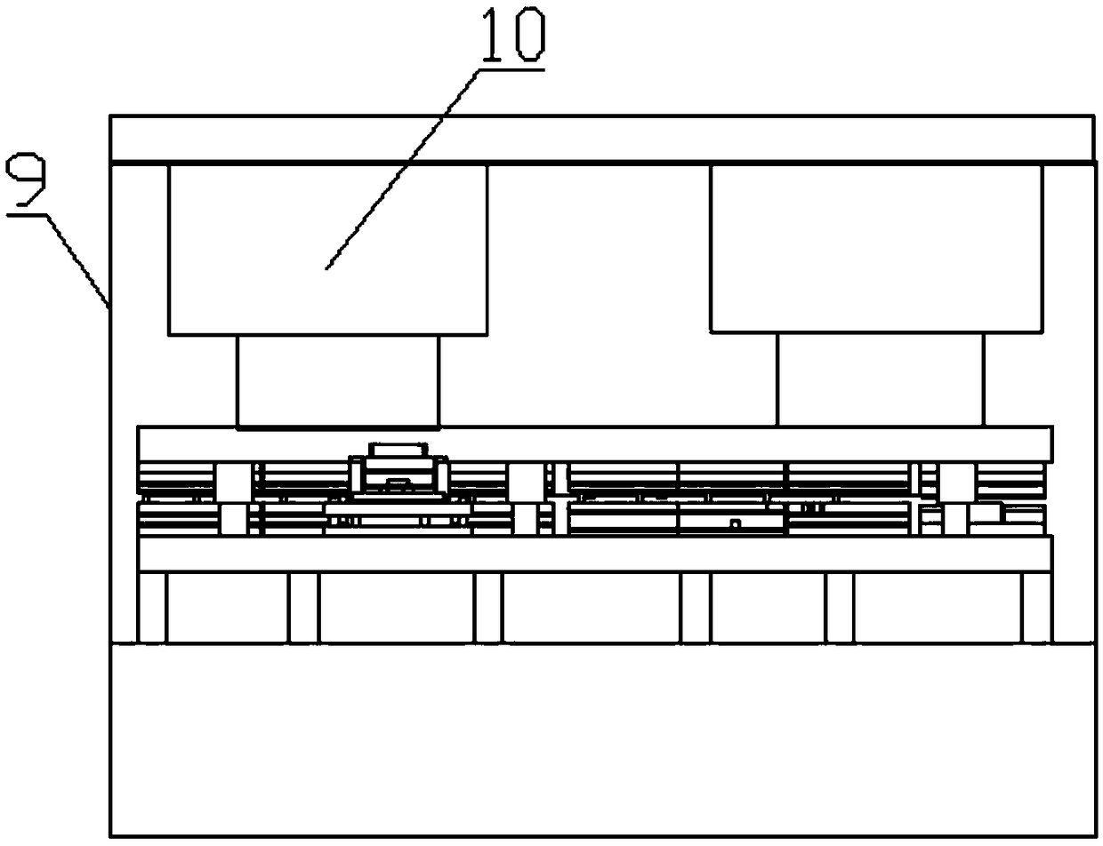
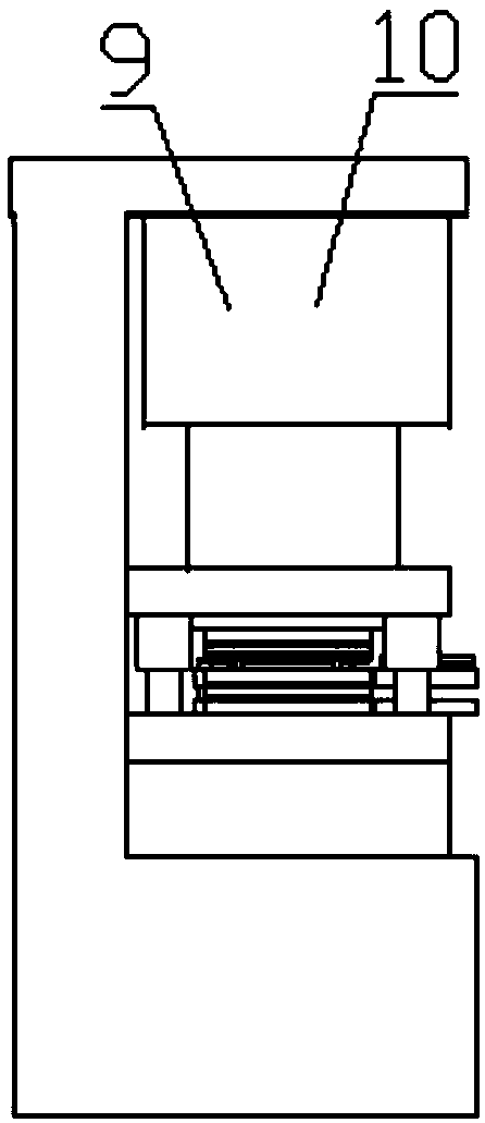
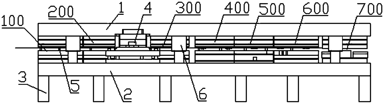
[0090] The structure of the processing machine tool of this embodiment is basically the same as that of the wiring box processing machine tool of embodiment 1, the difference is that the upper ends of the punching and tapping modules and the punching modules are along the direction of the feeding direction. Positioning columns 5 are installed on both sides, and the upper part of each positioning column 5 is provided with an annular groove 51 located on the same horizontal plane. The sheet material 7 passes through the annular groove 51 and is supported by the annular groove 51. Between column 5. This structure reduces the impact force when the upper and lower modules process the sheet material 7, and increases the service life of the machine tool. If the sheet material 7 is directly placed on the lower group mold for processing, a larger impact force is required to form the sheet material 7, which is easy to cause damage to the machine tool.

Embodiment 3

[0092] The processing machine tool of this embodiment is basically the same structure as the wiring cassette processing machine tool of Embodiment 2. The difference is that the upper mounting plate and the middle mounting plate of each upper group are connected by a spring. The movement of the upper mold acts as a buffer to reduce the impact force, and on the other hand, it also makes the working movement of the upper mold more smooth.


PUM


Abstract

The invention discloses a punching and tapping module for a wiring cassette machining machine tool, and belongs to the field of wiring cassette manufacturing. The punching and tapping module comprisesan upper mounting seat and a lower mounting seat which are mounted on a frame, wherein a first group module, a second group module, a tapping device and a third group module are successively installed in the upper mounting seat and the lower mounting seat in the feeding direction; the first group module is provided with a mounting hole punch, a connecting hole punch and an ear hole punch; the second group module is provided with a first batch of knockout hole punches and a second batch of knockout hole punches; the tapping device is provided with an ear hole screw tap; the third group moduleis provided with a third batch of knockout hole punches, a fourth batch of knockout hole punches and a lug hole punch. Punching and tapping operations can be performed on a plurality of positions on asheet material at the same time, the machining position is accurate, and the machining efficiency of the wiring cassettes by the machining machine tool is improved.

Description

technical field [0001] The invention belongs to the field of junction box manufacturing, and more specifically relates to a junction box processing machine tool and a punching and tapping module. Background technique [0002] In construction projects or various decoration constructions, in order to connect various cables in the room, it is usually necessary to open a groove on the wall, and then fix a junction box on the groove, the junction box can also serve as a connection Wires, as the transition of various electrical circuits and the protection of circuit safety, the wiring operation can be completed inside the cassette. [0003] The junction box is generally a rectangular box with an opening, consisting of a bottom plate and a number of side plates connected to the bottom plate. The side plates and the bottom plate are provided with wiring holes, threaded holes for subsequent installation, and mounting ears. Therefore, it is very difficult to process and form the junc...

Claims


Application Information

Patent Timeline
Patent Type & Authority Applications(China)
IPC IPC(8): B23P23/04
CPCB23P23/04Y02P70/10
Inventor 夏克周周浩夏欢欢
Owner 安徽省华夏机床制造有限公司
Why Eureka
Try Eureka