A crankshaft drilling and clamping device

A clamping device and crankshaft technology, applied in the field of crankshaft processing, can solve the problems such as the inability to adjust the punching angle according to the needs, the waste occupying a large space, and whether it is troublesome.

Active Publication Date: 2021-07-06
宁波健实机械有限公司
View PDF6 Cites 0 Cited by
  • Summary
  • Abstract
  • Description
  • Claims
  • Application Information

AI Technical Summary

Problems solved by technology

Along with the enlargement of crankshaft application range, some crankshafts need to be punched on the circumferential side of major axis, although there are some special-purpose punching fixtures in the prior art, can't adjust the rotation angle of punching relative to crank throw as required; It is troublesome to be able to adjust the operation; in addition, the waste generated during the drilling process has to be cleaned manually, because the waste is relatively fluffy and occupies a large space

Method used


Image

  • A crankshaft drilling and clamping device
  • A crankshaft drilling and clamping device
  • A crankshaft drilling and clamping device

Examples


Embodiment Construction

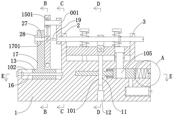
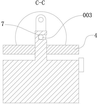
[0029] see Figure 1-10As shown, a crankshaft drilling clamping device includes a base 1, on which a left slide plate 2 and a right slide plate 3 are arranged side by side along the vertical direction upwards, on the base 1 there are left slide plate 2 and a right slide plate 3 A compression block 4 is vertically slidably connected between the right slide plates 3, and a first chute 401 is provided on the compression block 4 along the length direction perpendicular to the base 1, and the first chute 401 is slidably connected There is a compression pull plate 5, and the first screw rod 6 for driving the compression pull plate 5 to move along its length direction is connected in rotation in the first chute 401; the left slide plate 2 and the right slide plate 3 The first notch 7 for placing the long shaft 003 is provided on the side near the top position; notch 501 .

[0030] The base 1 is provided with four positioning slide bars 8 upwards in the vertical direction, and the p...


PUM


Abstract

The invention discloses a clamping device for crankshaft drilling, which comprises a base, a left slide plate and a right slide plate are arranged on the base, and a pressing block is arranged between the left slide plate and the right slide plate on the base, so that The pressing block is provided with a first chute, a pressing pull plate is slidably connected in the first chute, and a first screw rod is rotatably connected in the first chute; the left sliding plate and the right sliding plate are There is a first notch; the pressing pull plate is provided with a second notch; the base is provided with a plurality of positioning sliders, and the upper ends of the positioning sliders are threaded with adjusting bolts; the positioning sliders There is a compression spring on the upper sleeve; a transmission hole is provided in the base, a transmission screw is provided at the lower end of the compression block, and a driving cylinder is provided in the base; a short-axis crank throw fixing mechanism is provided on the base; the crankshaft is drilled The clamping device is not only simple in structure, but also can be properly adjusted according to the relative rotation angle of the punching hole and the crank throw.

Description

technical field [0001] The invention relates to the technical field of crankshaft processing, in particular to a crankshaft drilling and clamping device. Background technique [0002] The crankshaft is the main rotating mechanism of the engine, which is responsible for converting the up and down reciprocating motion of the piston into its own circular motion, and what we usually call the engine speed is the speed of the crankshaft. Such as Figure 10 The crankshaft shown includes a short shaft 001, a crank throw 002, and a long shaft 003 with positioning notches 30 at both ends, one end of the crank throw is fixedly connected to one end of the long shaft, and the other end of the crank throw is connected to the long shaft. One end of the minor axis is fixedly connected, and the minor axis and the major axis are parallel to each other. Along with the enlargement of crankshaft application range, some crankshafts need to be punched on the circumferential side of major axis, al...

Claims


Application Information

Patent Timeline
Patent Type & Authority Patents(China)
IPC IPC(8): B23Q3/08B23Q11/00
CPCB23Q3/062B23Q3/08B23Q11/0042B23Q2703/04B23Q2703/105
Inventor 王仁乔
Owner 宁波健实机械有限公司
Why Eureka
Try Eureka