Pushing mechanism

A push mechanism and push plate technology, applied in the field of machinery, can solve the problems of affecting the quality of finished products, unsatisfactory products, uneven force, etc., and achieve the effect of convenient operation, short processing time and uniform compression force

Inactive Publication Date: 2019-04-02
唐能慧
View PDF0 Cites 0 Cited by
  • Summary
  • Abstract
  • Description
  • Claims
  • Application Information

AI Technical Summary

Problems solved by technology

[0002] Huangba and Xueguanba are popular among consumers as traditional foods. During the production process, the raw materials need to be pushed into the forming mold after being evenly stirred, which is the most critical link. In the prior art, manual Complete, and the force is not un

Method used


Image

  • Pushing mechanism
  • Pushing mechanism
  • Pushing mechanism

Examples


Embodiment Construction

[0024] The specific implementation, structure, features and functions of the push mechanism proposed according to the invention will be described in detail below in conjunction with the accompanying drawings and preferred embodiments.

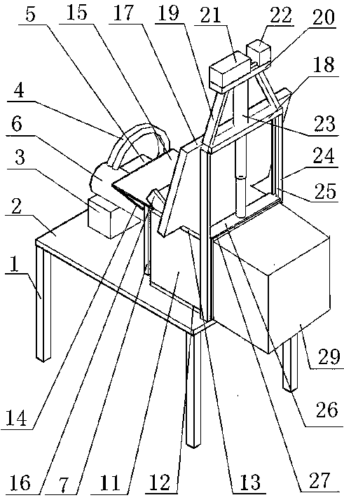
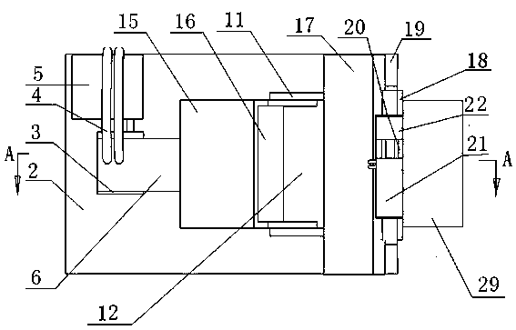
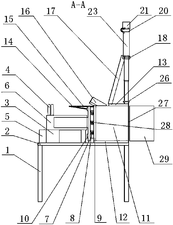
[0025] see figure 1 and Figure 8 , a pushing mechanism, comprising a panel 2, a buffer plate 7, a pusher plate 9, a positioning pin 10, a wall plate 11, a bottom plate 12, a top plate 13, a sealing plate 15, a feed port 16, a knife rest 26, and a molding die 29, It is characterized in that: there is a telescopic pump A6 on the panel 2, and the telescopic pump A6 is connected to the buffer plate 7, the buffer spring 8 and the trigger switch 28 are arranged on the buffer plate 7, the buffer spring 8 is connected to the pusher plate 9, and there is a bottom plate under the pusher plate 9 12. There is a wallboard 11 on the bottom plate 12, a top plate 13 and a feed port 16 on the top of the wall board 11, and a sealing plate 15 at the bottom of t...


PUM


Abstract

The invention discloses a pushing mechanism. The pushing mechanism comprises a panel, a buffer plate, a pushing plate, positioning pins, a wall plate, a bottom plate, a top plate, a sealing plate, a feeding inlet, a tool rest and a forming die. The pushing mechanism is characterized in that a telescopic pump A is arranged on the panel, the telescopic pump A is connected with the buffer plate, thebuffer plate is provided with a buffer spring and a trigger switch, the buffer spring is connected with the pushing plate, the bottom plate is arranged below the pushing plate, the bottom plate is provided with the wall plate, the top plate (13) and the feeding inlet are formed in the wall plate, the sealing plate is arranged at the bottom of the feeding inlet, the sealing plate is connected witha connecting plate, the connecting plate is connected with a positioning pin, the positioning pin is fixed to the pushing plate, the top plate is connected with a supporting plate, the supporting plate is connected with a supporting frame, the supporting frame is connected with a cross beam A, a longitudinal beam is arranged below the cross beam A, a sliding groove is formed in the longitudinal beam, the tool rest is arranged in the sliding groove, a telescopic pump B is connected to the upper part of the tool rest, a blade is arranged below the tool rest, and the forming die is arranged on the right side of the blade. The pushing mechanism is uniform in compression stress, simple in structure, convenient to operate, short in machining time, quick and practical.

Description

technical field [0001] The invention belongs to the mechanical field, in particular to a pushing mechanism. Background technique [0002] Huangba and Xueguanba are popular among consumers as traditional foods. During the production process, the raw materials need to be pushed into the forming mold after being evenly stirred, which is the most critical link. In the prior art, manual It is completed, and the force is not uniform when the material is compressed, which seriously affects the quality of the finished product. If there are many orders and large quantities, many workers are required to produce, which takes a long time and slow speed, which cannot meet the needs of the product on the market. Contents of the invention [0003] The purpose of the invention is to overcome the above disadvantages and provide a push mechanism with uniform compression force, simple structure, convenient operation, short processing time, fast and practical. [0004] The purpose of the inv...

Claims


Application Information

Patent Timeline
IPC IPC(8): B65G47/82A23P30/10A23L7/126
CPCB65G47/82A23L7/126A23P30/10B65G2201/0202
Inventor 唐能慧
Owner 唐能慧
Why Eureka
Try Eureka