A sealing profile for construction engineering decoration

A technology for construction engineering and profiles, applied in construction, building components, building structures, etc., can solve the problems of coating the joints of profiles, affecting the molding of profiles, and uneven coating of adhesive colloids, and achieve effective splicing. , the effect of uniform coating effect

Active Publication Date: 2020-12-08
广州茂润实验室设备科技有限公司
View PDF5 Cites 0 Cited by
  • Summary
  • Abstract
  • Description
  • Claims
  • Application Information

AI Technical Summary

Problems solved by technology

[0004] When using glue to splice profiles, the existing technology often assembles the profiles to be spliced ​​first, and then coats the joints of the profiles with adhesive colloid, or first coats the joint surface with adhesive colloid, and then For splicing, the former cannot effectively apply sufficient adhesive glue to the joints of the profiles, and the latter is likely to cause the problem of uneven coating of the adhesive gel, so these two methods will affect the bonding of the profiles

Method used


Image

  • A sealing profile for construction engineering decoration
  • A sealing profile for construction engineering decoration
  • A sealing profile for construction engineering decoration

Examples


Embodiment 1

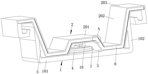
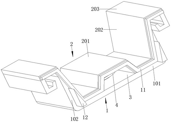
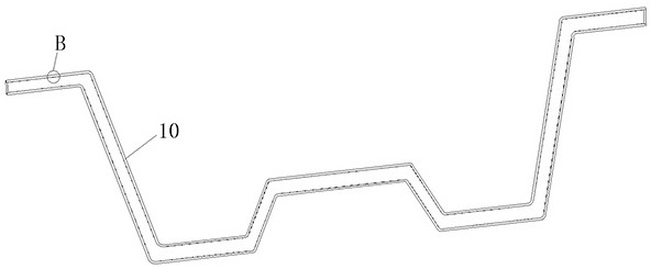
[0039] refer to figure 1 , figure 2 , image 3 , Figure 4 , Figure 5 , Figure 7 , a sealing profile for construction engineering decoration, including a support plate 1, a load-bearing plate 2, the load-bearing plate 2 is fixedly connected to the top of the support plate 1; an installation cavity is provided between the support plate 1 and the load-bearing plate 2 3. There is a sealing rubber tube 4 in the installation cavity 3, a storage cavity 5 is set on both sides of the installation cavity 3, and an air bag 6 is installed in the storage cavity 5, and the air bag 6 is connected to the sealing rubber tube 4 through the air pipe 7; There is a clamping groove 8, and the inner wall of the clamping groove 8 is provided with a serpentine installation groove 9, and the bottom wall of the serpentine installation groove 9 is fixedly connected with a serpentine rubber tube 10, and the top of the sealing rubber tube 4 is connected with the serpentine rubber tube 10 The other...

Embodiment 2

[0041] refer to figure 1 , figure 2 , image 3 , Figure 4 , Figure 5 , Figure 7 , a sealing profile for construction engineering decoration, including a support plate 1, a load-bearing plate 2, the load-bearing plate 2 is fixedly connected to the top of the support plate 1; an installation cavity is provided between the support plate 1 and the load-bearing plate 2 3. There is a sealing rubber tube 4 in the installation cavity 3, a storage cavity 5 is set on both sides of the installation cavity 3, and an air bag 6 is installed in the storage cavity 5, and the air bag 6 is connected to the sealing rubber tube 4 through the air pipe 7; There is a clamping groove 8, and the inner wall of the clamping groove 8 is provided with a serpentine installation groove 9, and the bottom wall of the serpentine installation groove 9 is fixedly connected with a serpentine rubber tube 10, and the top of the sealing rubber tube 4 is connected with the serpentine rubber tube 10 The other...

Embodiment 3

[0044] refer to figure 1 , figure 2 , a sealing profile for construction engineering decoration, which is basically the same as that of Embodiment 1, and furthermore, the top plate 201 is specifically a plate with a groove-shaped cross section, and the groove-shaped cross-section of the top plate 201 is conducive to forming the installation cavity 3, the wing The board 202 is inclined to the top board 201, and the obtuse angle between the wing board 202 and the top board 201 is 100-120 degrees.


PUM


Abstract

The invention discloses a seal section bar for decoration of architectural engineering, and belongs to the technical field of building section bars. The seal section bar comprises a shoe plate and a bearing plate, the bearing plate is fixedly connected to the top of the shoe plate, an installation cavity is arranged between the shoe plate and the bearing plate, a sealing rubber tube is arranged inthe installation cavity, the two sides of the installation cavity are provided with storage chambers respectively, and air bags are arranged in the storage chambers respectively and connected to thesealing rubber tube via gas tubes respectively; and a clamping groove is formed in the end surface of one side of the bearing plate, a snakelike installation groove is formed in the inner wall of theclamping groove, the bottom wall of the snakelike installation groove is fixedly connected with a snakelike glue transmission tube, and the top of the sealing rubber tube is connected with the snakelike glue transmission tube. Operation is convenient, the bonding glue is arranged inside the section bar, the bonding glue is uniformly extruded to the connection surface of the section bar by relativemovement of the section bar during splicing, the connection surface can be coated with sufficient bonding glue, and it can be ensured that the bonding glue is coated uniformly.

Description

technical field [0001] The invention relates to the technical field of building profiles, in particular to a sealing profile for construction engineering decoration. Background technique [0002] Profiles are objects with certain geometric shapes made of iron or steel and materials with certain strength and toughness (such as plastic, aluminum, glass fiber, etc.) through rolling, extrusion, casting, etc., and extrusion methods are used to produce profiles The extruded profiles are divided into two categories: hollow profiles and solid profiles. [0003] With the development of urban construction, the demand for profiles in the field of architectural decoration is increasing, especially for industrial buildings and large commercial buildings; in the process of using profiles for architectural decoration, the requirements for the size of profiles for buildings of different lengths , it is often necessary to splice multiple profiles together, and the splicing methods are mostl...

Claims


Application Information

Patent Timeline
Patent Type & Authority Patents(China)
IPC IPC(8): E04B9/06E04F13/22
CPCE04B9/064E04B9/10E04F13/0803
Inventor 不公告发明人
Owner 广州茂润实验室设备科技有限公司
Why Eureka
Try Eureka