tip turbine engine

A turbine engine and propeller tip technology, which is applied in the direction of engine components, turbine/propulsion device intake, charging system, etc., can solve problems such as aerodynamic performance matching, and achieve the effect of solving dynamic sealing problems

Active Publication Date: 2020-06-23
AECC HUNAN AVIATION POWERPLANT RES INST
View PDF5 Cites 0 Cited by
  • Summary
  • Abstract
  • Description
  • Claims
  • Application Information

AI Technical Summary

Problems solved by technology

[0003] The present invention provides a tip turbine engine to solve the dynamic sealing between the outlet of the compressor and the air inlet of the hollow fan, the air flow at the axial flow outlet of the compressor and the aerodynamic force at the inlet of the inner channel of the hollow fan existing in the existing tip turbine engine. Technical issues with performance matching

Method used


Image

  • tip turbine engine
  • tip turbine engine
  • tip turbine engine

Examples


Embodiment Construction

[0026] The embodiments of the present invention will be described in detail below with reference to the accompanying drawings, but the present invention can be implemented in many different ways defined and covered by the claims.

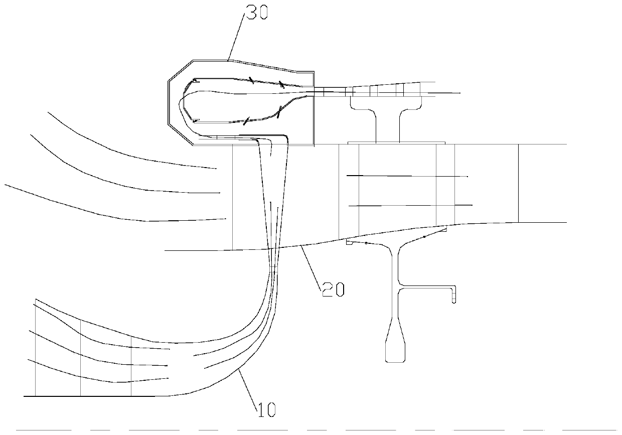
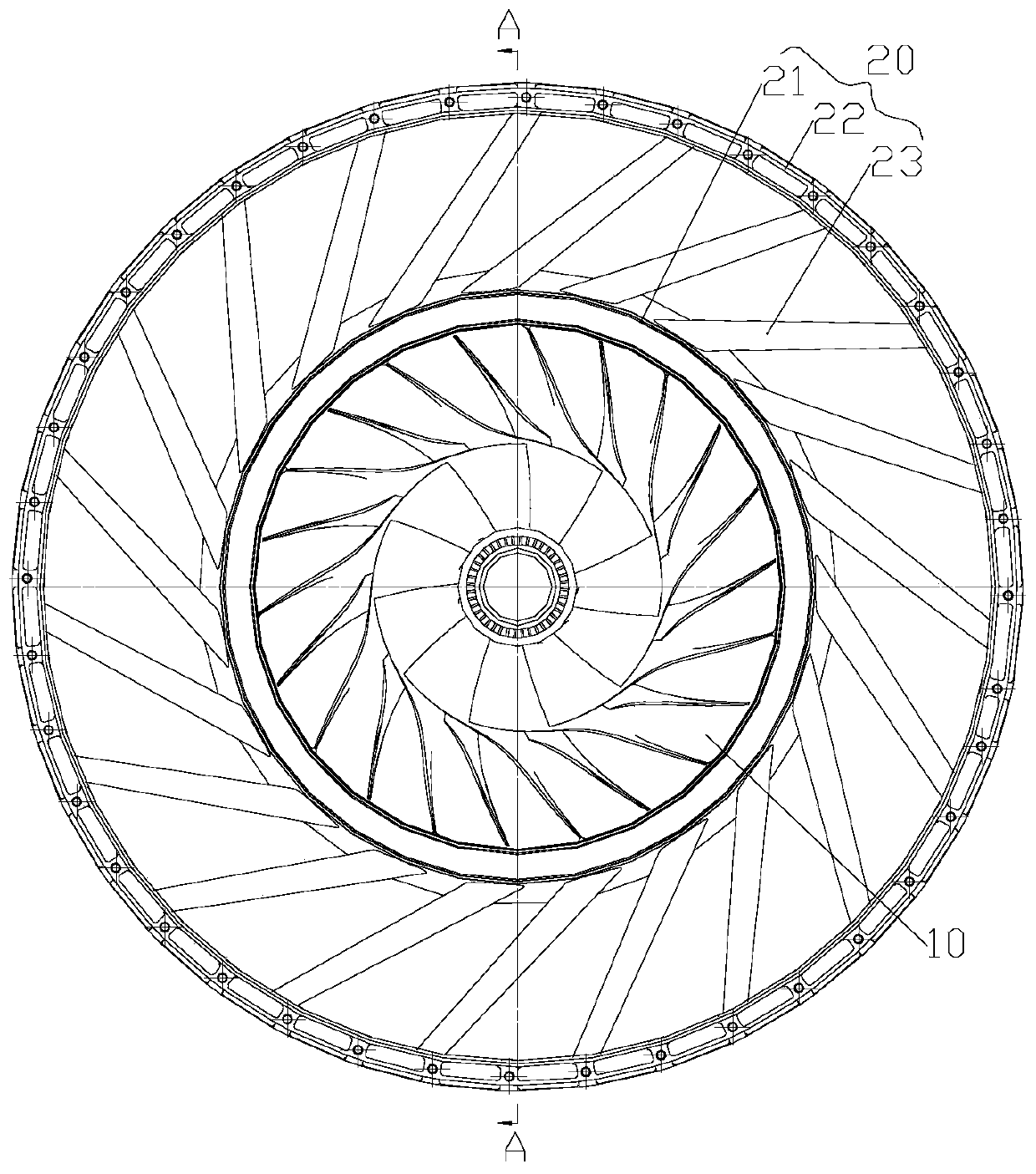
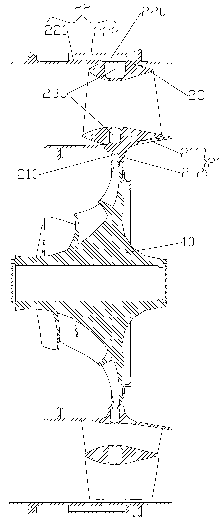
[0027] refer to figure 1 , the preferred embodiment of the present invention provides a blade-tip turbine engine, including: a high-pressure compressor 10 that is rotated, and the high-pressure compressor 10 is used to compress the incoming air along the axial direction and then flow out at high speed along its radial direction. The compressor 10 is covered with a fan stator 20 for diffusing and decelerating the incoming air and then flowing out. The fan stator 20 is ring-shaped and fixedly arranged. The outer duct of the fan stator 20 is provided with a combustion chamber 30 . The air intake end of the fan stator 20 is matched with the exhaust end of the high-pressure compressor 10, so that the high-speed airflow flowing out of the high-pressure co...


PUM


Abstract

The invention discloses a paddle tip turbine engine. The paddle tip turbine engine comprises a rotary high-pressure compressor. The high-pressure compressor is used for compressing incoming flow air flowing in the axial direction of the high-pressure compressor and driving the incoming flow air to flow out of the radial direction of the high-pressure compressor at the high speed. A fan stator is mounted outside the high-pressure compressor in a sleeving manner, wherein the fan stator is used for conducting pressure expansion and speed reduction on the incoming flow air and driving the incomingflow air to flow out. The fan stator is in a ring shape and is arranged fixedly. A combustion chamber is formed in an outer duct of the fan stator. The air inlet end of the fan stator is designed tobe matched with the exhaust end of the high-pressure compressor so that the fan stator can be used for driving high-speed air flow flowing out of the high-pressure compressor to flow into the fan stator. The exhaust end of the fan stator is designed to be matched with the air inlet end of the combustion chamber so that the air flow formed after pressure expansion and speed reduction of the fan stator can be driven to flow into the combustion chamber. The high-pressure compressor can meet reversing, from the axial direction to the radial direction, of the air flow; no technical obstacle exists;and the problem of matching between air flow of an axial flow outlet of an existing compressor and pneumatic performance of an inlet of a flow channel inside a hollow fan is solved.

Description

technical field [0001] The invention relates to the field of aeroengines, in particular to a tip turbine engine. Background technique [0002] The short-distance, vertical take-off and landing aircraft can greatly reduce the special requirements for airports, and is especially suitable for use in disaster relief and maritime environments. Its military and civilian potential is huge. At the beginning of this century, foreign countries began to carry out research on the principle of propeller-tip turbofan engines that can be used for short-distance, vertical take-off and landing aircraft. Then push the turbine installed on the blade tip of the hollow fan to drive the rotation of the hollow fan. The hollow fan generates most of the thrust for the incoming flow boost. At the same time, the hollow fan drives part of the power generated by the turbine through the speed increaser to drive the axial flow compressor to run. In the tip turbofan engine, due to the need to solve the dy...

Claims


Application Information

Patent Timeline
Patent Type & Authority Patents(China)
IPC IPC(8): F02C7/04
CPCF02C7/04
Inventor 吕顺日周进景晓明
Owner AECC HUNAN AVIATION POWERPLANT RES INST
Why Eureka
Try Eureka