
A full metal seal pilot safety valve

A pilot-operated safety valve, all-metal technology, used in safety valves, valve devices, balance valves, etc., can solve the problems of limited high temperature resistance of non-metallic materials, inability to apply sealing specific pressure, and inability to meet market demand, etc. The effect of movement reliability

Active Publication Date: 2019-02-01
BEIJING AEROSPACE PETROCHEM TECH & EQUIP ENG CORP LTD
View PDF6 Cites 0 Cited by
  • Summary
  • Abstract
  • Description
  • Claims
  • Application Information

AI Technical Summary

Problems solved by technology

[0003] Due to the limitation of the structure, the conventional pilot-operated safety valve can only provide a limited sealing specific pressure at the key dynamic sealing position, and cannot apply the metal hard sealing form with high sealing specific pressure requirements. Therefore, the existing structure uses a large amount of rubber at the sealing position. Non-metallic materials such as O-rings or fluoroplastics
However, the high temperature resistance of non-metallic materials is limited. Even the perfluoroether rubber O-ring with the best relative temperature resistance has a maximum service temperature of only 320°C, which greatly limits the use of pilot-operated safety valves under high temperature conditions.
[0004] At present, domestic petrochemical and electric power industries are developing rapidly. Many large-scale MTO, PX and other devices require a large number of pilot-operated safety valves. With more and more high-temperature and high-pressure working conditions in the chemical industry, conventional O-ring sealed pilot-operated safety valves have become Unable to meet market demand, the market urgently needs to design a pilot-operated safety valve that can meet harsh high-temperature conditions

Method used


Image

  • A full metal seal pilot safety valve
  • A full metal seal pilot safety valve
  • A full metal seal pilot safety valve

Examples


Embodiment Construction

[0026] The present invention will be described in further detail below in conjunction with the accompanying drawings and specific embodiments.

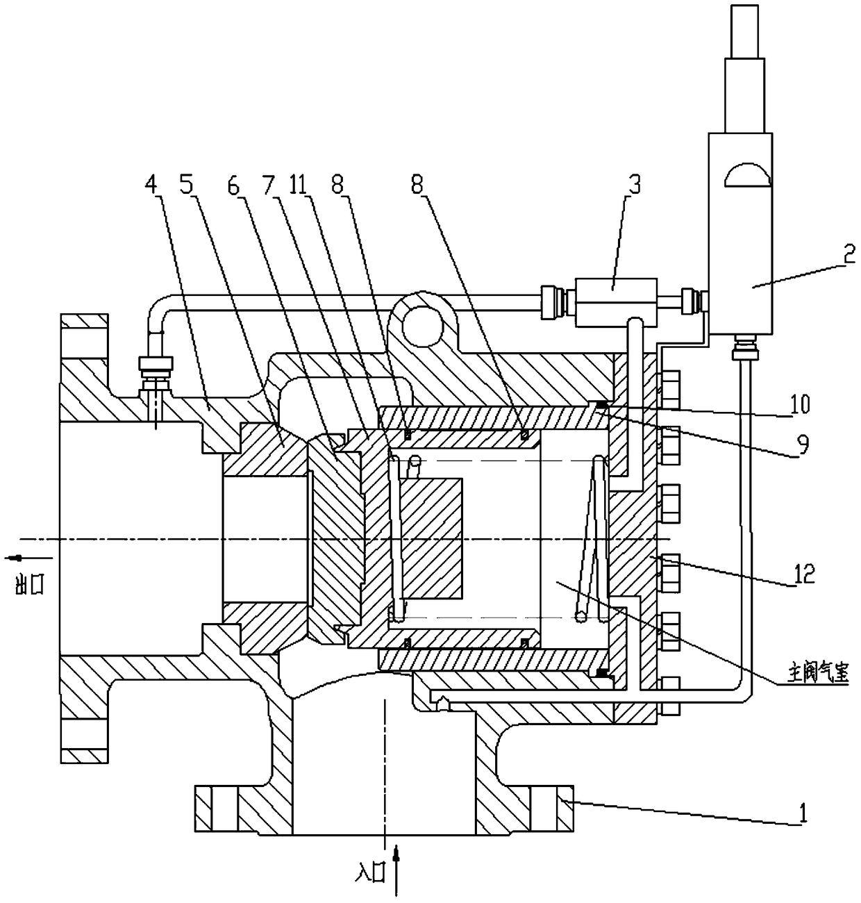
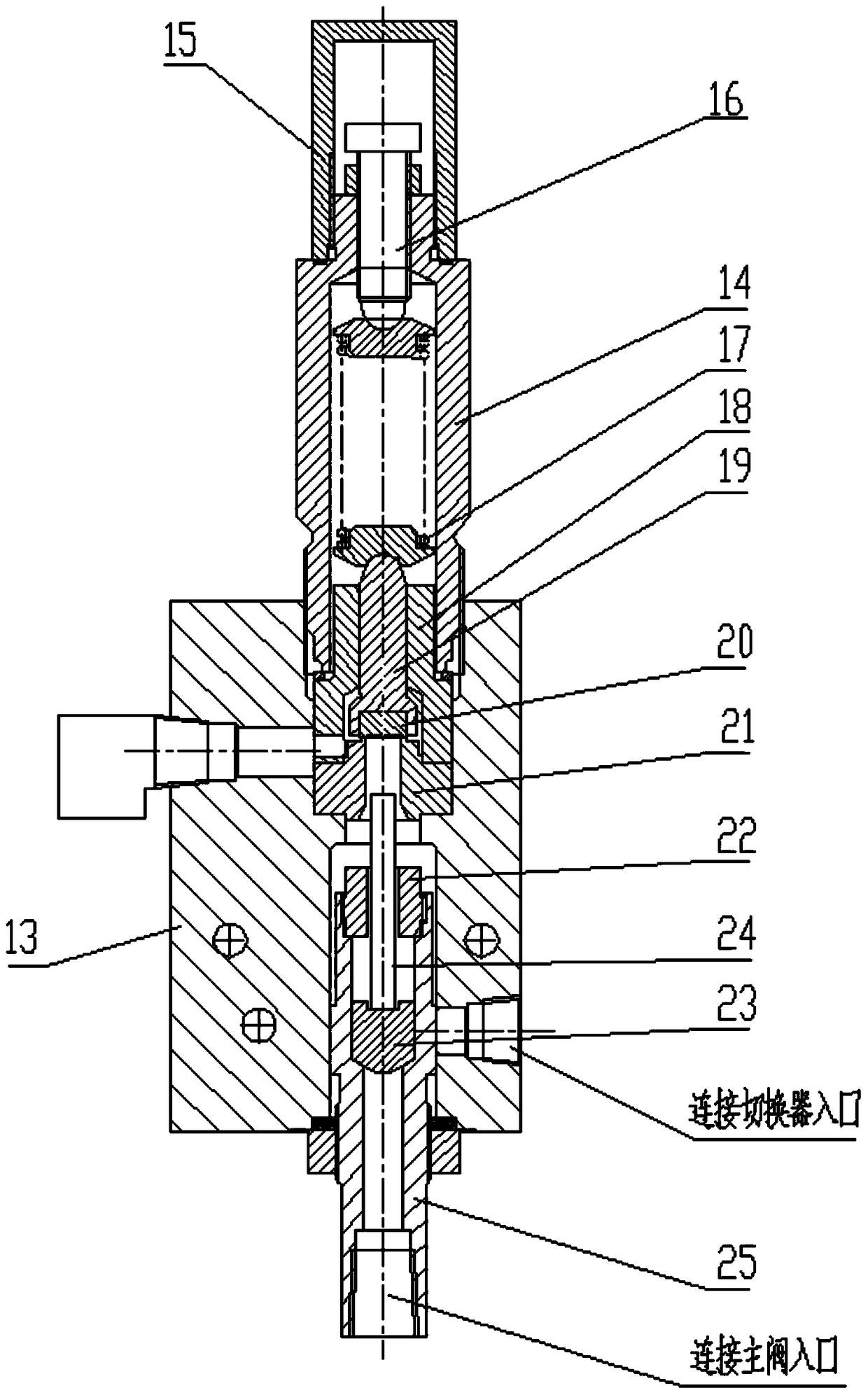
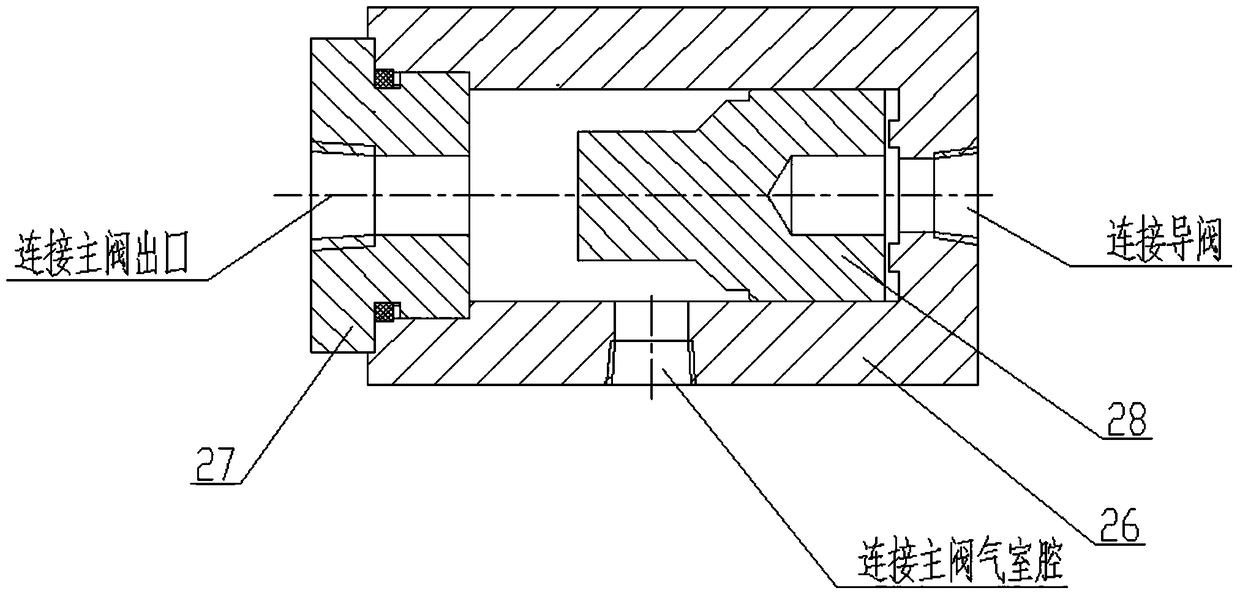
[0027] Such as figure 1 As shown, the full metal seal pilot safety valve is composed of main valve 1, pilot valve 2 and switcher 3. The pilot valve 2 is respectively connected with the inlet of the main valve and the inlet of the switch 3 through pressure pipes. The three passages on the switcher 3 are respectively connected with the inlet of the pilot valve, the cavity of the air chamber of the main valve and the outlet of the main valve by means of pressure pipes.

[0028] The main valve 1 is composed of the main valve body 4, the main valve seat 5, the main valve disc 6, the piston 7, the sealing ring 8, the main valve guide sleeve 9, the graphite pad 10, the main valve spring 11, and the cover plate 12.

[0029] The lower end of the main valve body 4 is an inlet, and one side is processed with an outlet, and both the inlet and t...


PUM


Abstract

The invention belongs to a pressure system overpressure protection technology, and particularly discloses an all-metal-sealed pilot-type safety valve. The all-metal-sealed pilot-type safety valve is composed of a main valve, a pilot valve and a switcher. The pilot valve is connected with a main valve inlet and a switcher inlet. The switcher is connected with a pilot valve inlet, a main valve air chamber and a main valve outlet. A main valve seat is fixed to a main valve body. A main valve flap is connected with a piston in a threaded manner. After a main valve guide sleeve and the main valve body are mounted, a cover plate is connected with the main valve body through a bolt. A valve deck is fixed to a pilot valve body through a thread. A guide valve spring is located in the valve deck and directly acts on a valve shaft. A valve bonnet is fixed to the portion above the valve deck. The valve flap of the main valve is opened or closed in the horizontal direction. Main valve main seal is only the seal between the valve seat and the valve flap. The possibility of leakage to the outlet from the main valve air chamber is avoided effectively, and possible leakage points of the valve are reduced to the maximum. The sealing ring structure design is adopted between the main valve guide sleeve and the valve flap. The problem about movable seal of the piston at the high temperature is solved.

Description

technical field [0001] The invention belongs to valve technology, in particular to a pilot safety valve. Background technique [0002] Pilot-operated safety valve is a non-direct-acting safety valve, which consists of a main valve and a pilot valve, and relies on the medium discharged by the pilot valve to drive or control the opening of the main valve. The pilot valve type safety valve has the remarkable advantages of allowing the working pressure to be very close to the set pressure, the action performance is not affected by the back pressure, it can be fully opened quickly with a small overpressure, and the structure is compact. [0003] Due to the limitation of the structure, the conventional pilot-operated safety valve can only provide a limited sealing specific pressure at the key dynamic sealing part, and cannot apply the metal hard sealing form with high sealing specific pressure requirements. Therefore, the existing structure uses a large amount of rubber at the sea...

Claims


Application Information

Patent Timeline
Patent Type & Authority Patents(China)
IPC IPC(8): F16K17/04
CPCF16K17/04
Inventor 鲍鲜宇娄少华王亦逍于红辉郭清云陈殿京王学彬
Owner BEIJING AEROSPACE PETROCHEM TECH & EQUIP ENG CORP LTD
Learn More