Negative flow hydraulic control oil circuit and hydraulic system and excavator

A technology for controlling oil passage and negative flow, which is applied in earth movers/shovels, fluid pressure actuating devices, mechanical equipment, etc. It can solve the problem of high fuel consumption, reduce oil temperature, save energy, and avoid overflow loss Effect

Inactive Publication Date: 2019-01-15
LIUZHOU LIUGONG EXCAVATORS +2
View PDF8 Cites 2 Cited by
  • Summary
  • Abstract
  • Description
  • Claims
  • Application Information

AI Technical Summary

Problems solved by technology

[0004] The technical problem to be solved by the present invention is to provide a negative flow hydraulic control hydraulic system for the problem that the main pump in the existing negative flow hydraulic control hydraulic system generates a large system overflow flow when the main pump is running at high pressure and full power, resulting in high fuel consumption. The negative flow hydraulic control oil circuit of the hydraulic system makes the negative flow hydraulic control hydraulic system reduce the power and displacement of the main pump when the hydraulic system is under high pressure conditions, reducing overflow loss and energy consumption

Method used


Image

  • Negative flow hydraulic control oil circuit and hydraulic system and excavator
  • Negative flow hydraulic control oil circuit and hydraulic system and excavator
  • Negative flow hydraulic control oil circuit and hydraulic system and excavator

Examples


Embodiment 1

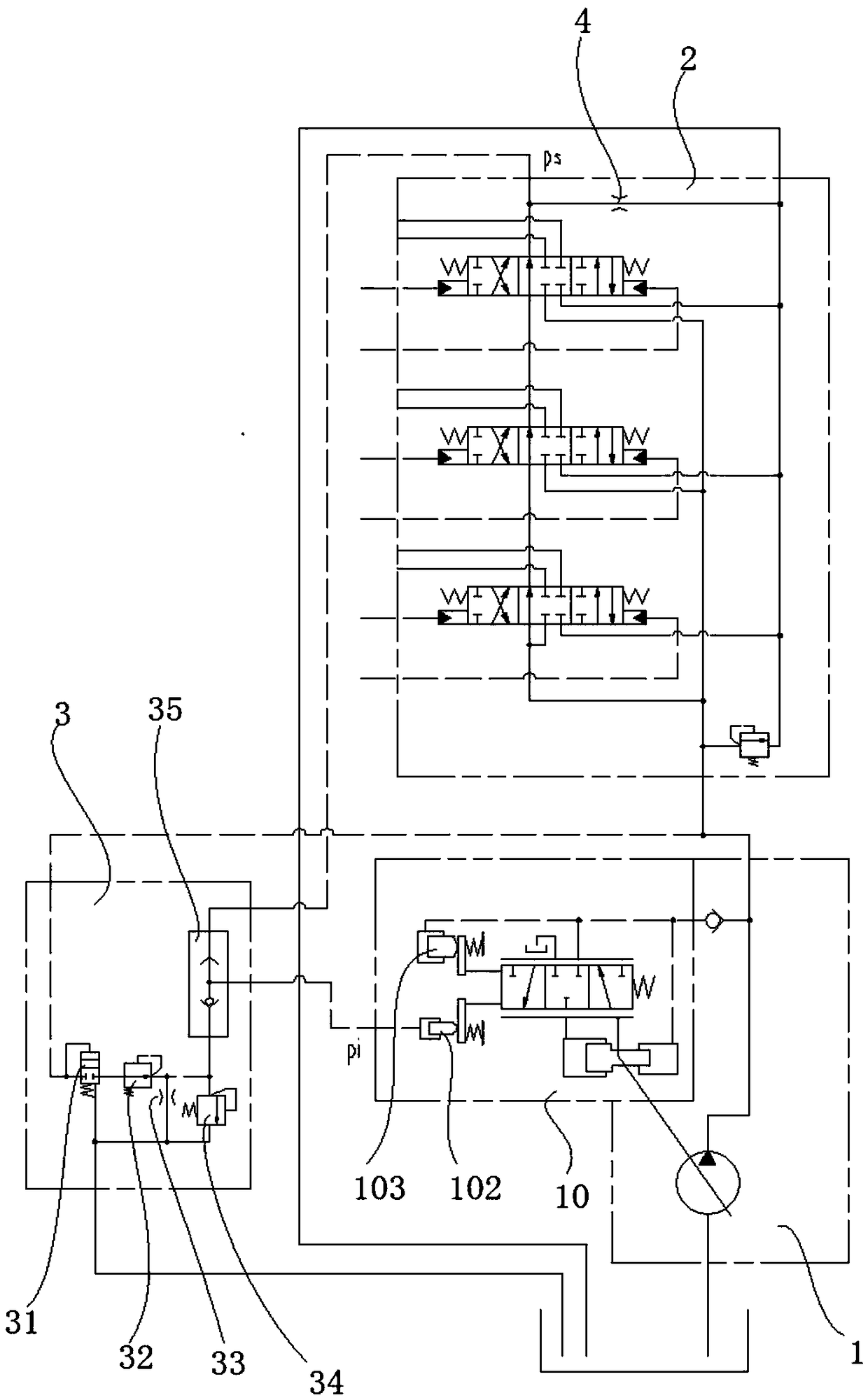
[0019] Such as figure 1 As shown, in this embodiment, the negative flow hydraulic control oil circuit includes the main pump 1, the main control valve 2 connected to the pump port of the main pump 1, and the pressure cut-off valve 3. The middle position oil return channel of the main control valve 2 is provided with The middle oil return orifice 4, the pressure cut-off valve 3 includes a hydraulic control reversing valve 31, a pressure reducing valve 32, and a shuttle valve 35. The hydraulic control end of the hydraulic control reversing valve 31 is connected to the oil inlet and the oil inlet passes through The pipeline is connected to the pump port of the main pump 1, the oil inlet end of the pressure reducing valve 32 is connected to the oil outlet end of the hydraulic control reversing valve 31 and the oil outlet end of the pressure reducing valve is connected to the second oil inlet end of the shuttle valve 35, The first oil inlet end of the shuttle valve 35 is connected ...

Embodiment 2

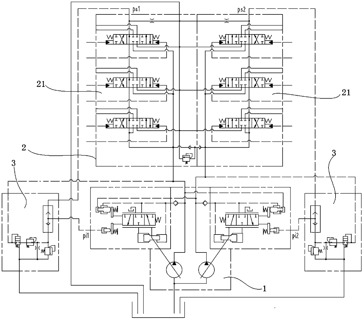
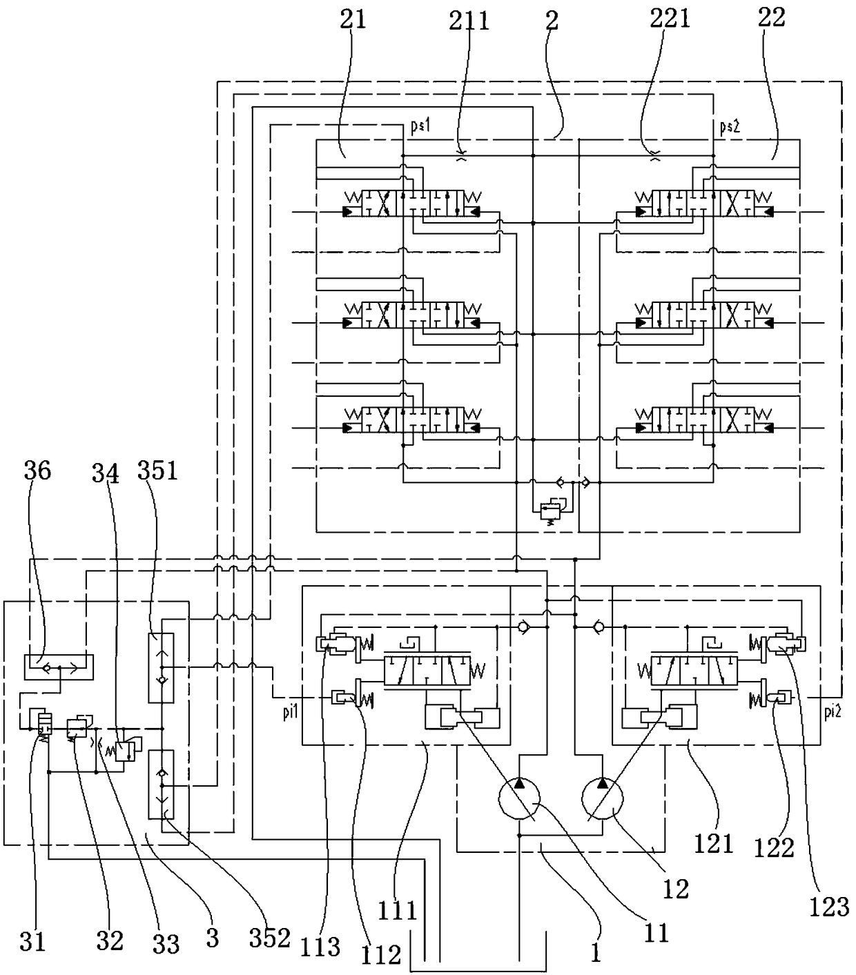
[0022] Such as image 3As shown, the negative flow hydraulic control oil circuit in this embodiment includes a main pump 1 , a main control valve 2 connected to the pump port of the main pump, a neutral oil return orifice, and a pressure cut-off valve 3 . The main pump 1 includes a left pump 11 and a right pump 12, and the main control valve 2 includes a first main control valve group 21 connected to the pump port of the left pump 11 and a second main control valve group 22 connected to the pump port of the right pump 12, each Each main control valve group includes several joint control valves for controlling different hydraulic actuators. The middle oil return orifice includes a first middle oil return orifice 211 arranged on the middle oil return passage of the first main control valve group 21 and a first middle oil return orifice 211 arranged on the middle oil return passage of the second main control valve group 22 The second neutral oil return orifice 221. The pressure...


PUM


Abstract

The invention relates to a hydraulic control oil circuit, and provides a negative flow hydraulic control oil circuit in order to solve the problems of high oil consumption and high oil temperature caused by large overflow flow when a main pump operates at high pressure and full power in an existing negative flow hydraulic control system. The negative flow hydraulic control oil circuit comprises amain pump, a main control valve and a pressure shutoff valve. A neutral position oil returning throttle hole is formed in a neutral position oil returning channel of the main control valve, and the pressure cut-off valve includes a normally closed hydraulic control reversing valve, a pressure reducing valve and a shuttle valve. The liquid control end of the hydraulic control reversing valve is connected with the oil inlet end, and a pump opening of the main pump is connected with the oil inlet end through a pipe. The oil inlet end of the pressure reducing valve is connected with the oil outletend of the hydraulic control reversing valve, and the oil outlet end of the pressure reducing valve is connected with the second oil inlet end of the shuttle valve. The first oil inlet end of the shuttle valve is connected with the oil inlet end of the neutral position oil returning throttle hole, and a negative flow displacement controller of a main pump displacement regulator is connected withthe oil outlet end of the shuttle valve. According to the negative flow hydraulic control oil circuit, the displacement of the main pump is reduced when a machine operates under high pressure conditions, so that the main pump can operate at low power, high flow overflow loss is avoid, energy is saved, and the oil temperature is reduced.

Description

technical field [0001] The invention relates to a hydraulic control oil circuit, more specifically, to a negative flow hydraulic control oil circuit, a hydraulic system and an excavator. Background technique [0002] Negative flow hydraulic control hydraulic system is widely used in medium and large excavators and is a very mature hydraulic system. It is characterized in that an orifice is set on the middle oil return channel of the main control valve, and the oil passes through the orifice to generate a pressure difference. Lead the pressure in front of the orifice to the negative flow displacement controller of the displacement regulator of the hydraulic pump to control the displacement of the hydraulic pump to prevent large air flow loss in the system. When the whole machine is in standby operation (or the operator is doing fine work), the hydraulic oil (or remaining hydraulic oil) output by the main pump flows back to the oil tank through the middle oil return channel of...

Claims


Application Information

Patent Timeline
Patent Type & Authority Applications(China)
IPC IPC(8): F15B11/00F15B13/02E02F9/22
CPCE02F9/22F15B11/00F15B13/02
Inventor 玉有恩韦会周
Owner LIUZHOU LIUGONG EXCAVATORS
Why Eureka
Try Eureka