Deep groove sealing sampler

A technology of deep groove sealing and sampler, which is applied in the field of sampler, can solve the problems that the sampling spoon can only get to the surface of the pulp, affect the process inspection progress, and cannot provide effective data, etc., so as to reduce the cost of labor and pump sampling, The effect of improving sampling work efficiency and reducing sampling frequency

Pending Publication Date: 2019-01-15
YUNNAN HUALIAN ZINC & INDIUM
View PDF0 Cites 0 Cited by
  • Summary
  • Abstract
  • Description
  • Claims
  • Application Information

AI Technical Summary

Problems solved by technology

[0002] In the non-ferrous metal beneficiation industry, sampling inspection is essential. Most beneficiation plants face major problems in deep tank sampling. Deep tank sampling requires high precision. Ordinary sampling spoons can only get to the surface of the pulp
However, the traditional long sampling spoon is more difficult to operate, generally requires two people to operate, the sampling volume is small, the length of the sampling spoon cannot be adjusted and the sampling is not accurate, especially for the whole process inspection of the dressing plant, it is necessary to use a large number of pumps for deep The cost of tank sampling is high, which seriously affects the process inspection progress of the process, and cannot provide effective data to guide production. Moreover, for the ore samples in the pump pool, due to operational problems, it is more dangerous to take samples on the mine pump pool.

Method used


Image

  • Deep groove sealing sampler
  • Deep groove sealing sampler
  • Deep groove sealing sampler

Examples


Embodiment 1

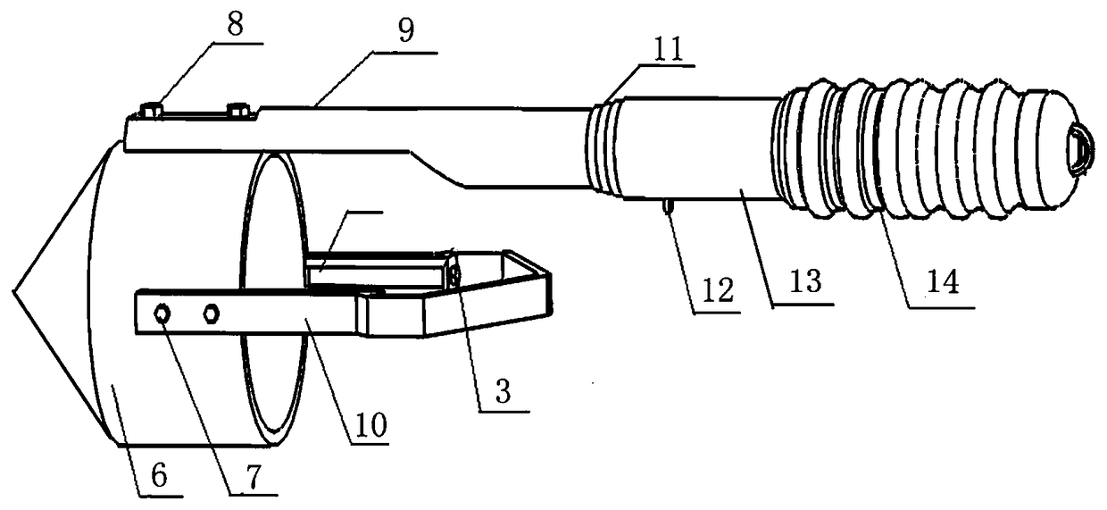
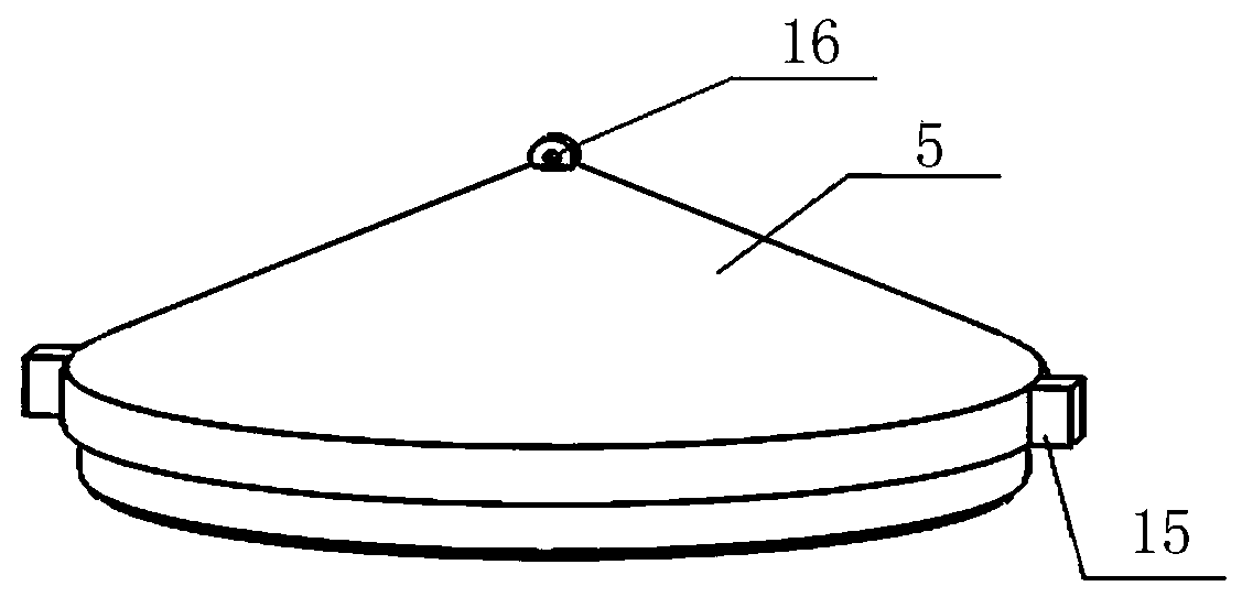
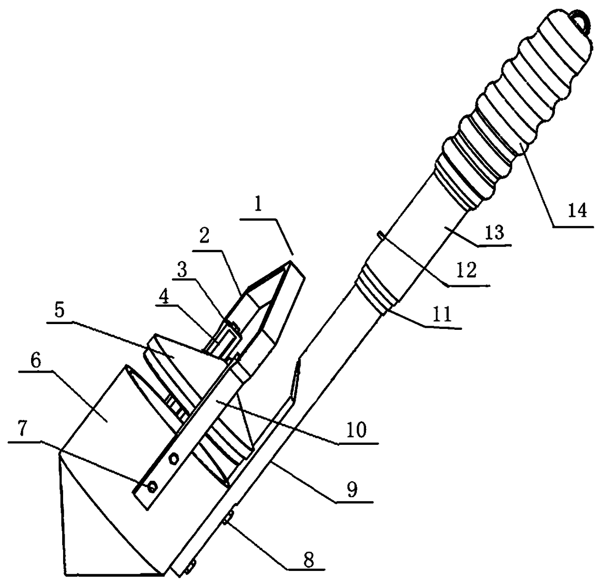
[0020] Embodiment 1: as Figure 1-3 As shown, a deep groove sealed sampler includes a support 1, a guide groove 4, a guide block 15, a pot cover 5, and a pot body 6. The pot body 6 is a cylindrical container, and its outer bottom is conical. The bracket 1 is fixed on the outer wall of the pot body 6 through connecting bolts A 7 and is in the shape of a handle. The bracket 1 is composed of a vertical part 10 and a cap top 2. The vertical part 10 of the bracket 1 has a guide groove 4 inside. There is a guide block 15 on the edge of the pot lid 5 that matches the guide groove 4. The pot lid 5 can slide up and down along the guide groove 4. The top of the pot lid 5 is provided with a hanging hole, and the traction rope is tied to the hanging hole.

Embodiment 2

[0021] Embodiment 2: as Figure 1-3 As shown, a deep groove sealed sampler includes a support 1, a guide groove 4, a guide block 15, a pot cover 5, and a pot body 6. The pot body 6 is a cylindrical container, and its outer bottom is conical. The bracket 1 is fixed on the outer wall of the pot body 6 through connecting bolts A 7 and is in the shape of a handle. The bracket 1 is composed of a vertical part 10 and a cap top 2. The vertical part 10 of the bracket 1 has a guide groove 4 inside. There is a guide block 15 matching the guide groove 4 on the edge of the pot cover 5, and the pot cover 5 can slide up and down along the guide groove 4. The top of the pot cover 5 is provided with a hanging hole, and the traction rope is tied to the hanging hole; the sampler Also comprise a telescoping rod, described telescoping rod is divided into hand-held part 14, telescoping part 11, connecting part 9 three parts, described connecting part 9 is fixed on the kettle body 6 by connecting b...

Embodiment 3

[0022] Embodiment 3: as Figure 1-3 As shown, a deep groove sealed sampler includes a support 1, a guide groove 4, a guide block 15, a pot cover 5, and a pot body 6. The pot body 6 is a cylindrical container, and its outer bottom is conical. The bracket 1 is fixed on the outer wall of the pot body 6 through connecting bolts A 7 and is in the shape of a handle. The bracket 1 is composed of a vertical part 10 and a cap top 2. The vertical part 10 of the bracket 1 has a guide groove 4 inside. There is a guide block 15 on the edge of the pot cover 5 that matches the guide groove 4, and the pot cover 5 can slide up and down along the guide groove 4. At the end of the guide groove 4, there is a bar 3 that prevents the guide block 15 from slipping out. The top of the cover 5 is provided with a hanging hole, and the traction rope is tied on the hanging hole; the sampler also includes a telescopic rod, and the telescopic rod is divided into three parts: a hand-held part 14, a telescopi...


PUM


Abstract

The invention provides a deep groove sealing sampler, a sampler in particular to an ore pulp sampler, which comprises a support, a guide groove, a guide block, a pot lid, and a body, wherein the bodyis a cylindrical container, the outer bottom of the body is conical, the support is fixed to the outer wall of the body through connecting bolt A and is a handle shape. The deep groove sealing samplerimproving the sampling precision, reducing the difficulty of operation, and has great help in guiding the production of the process.

Description

technical field [0001] The invention relates to a sampler, in particular to a sampler for ore pulp. Background technique [0002] In the non-ferrous metal beneficiation industry, sampling inspection is essential. Most beneficiation plants face major problems in deep tank sampling. Deep tank sampling requires high precision, and ordinary sampling spoons can only get to the surface of the pulp. However, the traditional long sampling spoon is more difficult to operate, generally requires two people to operate, the sampling volume is small, the length of the sampling spoon cannot be adjusted and the sampling is not accurate, especially for the whole process inspection of the dressing plant, it is necessary to use a large number of pumps for deep The cost of tank sampling is high, which seriously affects the process inspection progress of the process, and cannot provide effective data to guide production. Moreover, for the ore samples in the pump pool, due to operational problems...

Claims


Application Information

Patent Timeline
Patent Type & Authority Applications(China)
IPC IPC(8): G01N1/10
CPCG01N1/10G01N2001/1031
Inventor 王硕许维维兰希雄李前进秦龙斌李永芬牛珊
Owner YUNNAN HUALIAN ZINC & INDIUM
Why Eureka
Try Eureka