Stimulated emission loss fluorescent lifetime super-resolution imaging device

A technology of stimulated emission loss and super-resolution imaging, which is applied in the direction of material excitation analysis, measurement devices, fluorescence/phosphorescence, etc., can solve the problem of low imaging accuracy and achieve the effect of improving accuracy

Inactive Publication Date: 2019-01-15
SHENZHEN UNIV
View PDF5 Cites 14 Cited by
  • Summary
  • Abstract
  • Description
  • Claims
  • Application Information

AI Technical Summary

Benefits of technology

This patented technology allows for improved resolution during image capturing compared to traditional methods like scanning electron microscopy (SEM). By utilizing an activated emitter called pump light instead of just one type of laser beam, which helps reduce background noise from other sources such as ambient lights. When this technique uses two different types of lasers - either exciting red dye lamps at high wavelengths near 780 nm) or alternating between blue/green LED's and yellow phosphors at lower wavenumber levels, these techniques allow us to capture images more accurately than older methods.

Problems solved by technology

This patented technical problem addressed in the patents relates to improving the performance of Optics systems used for creation of images through their ability to capture minute amounts of radiation accurately without damaging samples or causing unwanted effects such as photosensitivity decay caused by ultraviolet ray exposure.

Method used


Image

  • Stimulated emission loss fluorescent lifetime super-resolution imaging device

Examples


Embodiment Construction

[0019] In order to make the purpose, features and advantages of the present invention more obvious and understandable, the technical solutions in the embodiments of the present invention will be clearly and completely described below in conjunction with the accompanying drawings in the embodiments of the present invention. Obviously, the described The embodiments are only some of the embodiments of the present invention, but not all of them. Based on the embodiments of the present invention, all other embodiments obtained by those skilled in the art without making creative efforts belong to the protection scope of the present invention.

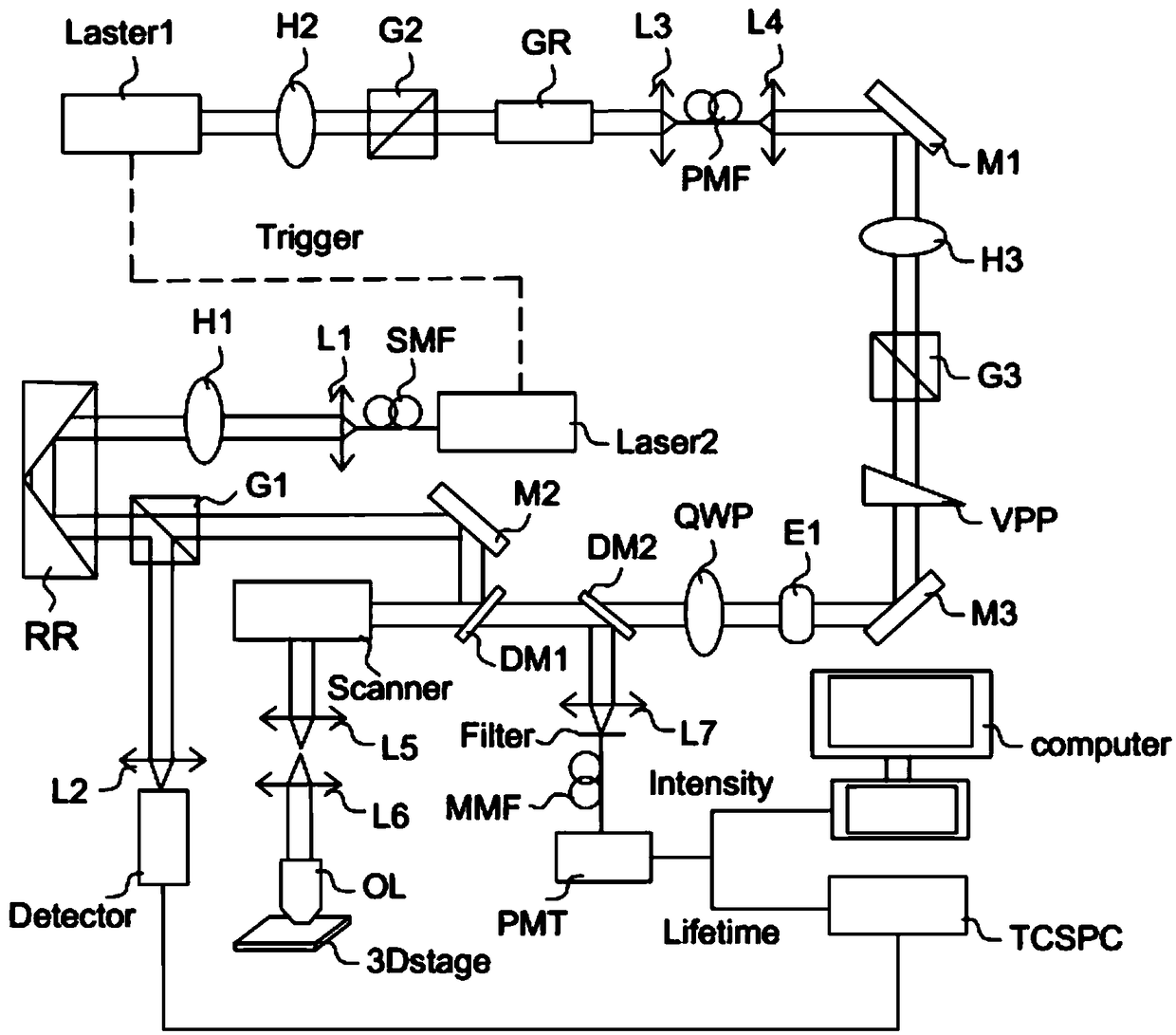
[0020] see figure 1 , is a stimulated emission loss fluorescence lifetime super-resolution imaging device, comprising: a loss laser supply part, a loss laser adjustment component, an excitation laser supply part, a synchronization controller, an excitation laser adjustment component, a spiral phase plate VPP, a slide QWP, The second dichroma...


PUM


Abstract

The invention discloses a stimulated emission loss fluorescent lifetime super-resolution imaging device for live cell imaging. The problem that the live cell imaging precision is low in the prior artis solved. The imaging device comprises a loss laser provider, a loss laser regulating module arranged at an output end of the loss laser provider, an excitation laser provider arranged at one side ofthe loss laser provider, a synchronization controller arranged between the excitation laser provider and the loss laser provider, an excitation laser regulating module arranged at the output end of the excitation laser provider, a spiral phase plate arranged at one side of the loss laser regulating module, a slide arranged at one side of the spiral phase plate, a second dichroic mirror arranged at one side of the slide, a first dichroic mirror arranged at one side of the second dichroic mirror, a sample fluorescent collection module arranged at one side of the first dichroic mirror, a florescent imaging module arranged at one side of the second dichroic mirror, and a reference fluorescent signal collecting module arranged at one side of the excitation laser regulating module, thereby improving the live cell imaging precision.

Description


Claims


Application Information

Patent Timeline
Owner SHENZHEN UNIV
Why Eureka
Try Eureka