Traction sheave elevator and drive machine unit

A driving device and sheave-type technology, which is applied to elevators, transportation and packaging, elevators, etc. in buildings, can solve problems such as increasing the cross-section of elevator shafts, reduce rope wear, reduce supporting force, and save buildings effect of space

Inactive Publication Date: 2002-10-09
KONE CORP
View PDF5 Cites 4 Cited by
  • Summary
  • Abstract
  • Description
  • Claims
  • Application Information

AI Technical Summary

Problems solved by technology

This means that the distance between the two should be at least the diameter of the traction

Method used


Image

  • Traction sheave elevator and drive machine unit
  • Traction sheave elevator and drive machine unit
  • Traction sheave elevator and drive machine unit

Examples


Example Embodiment

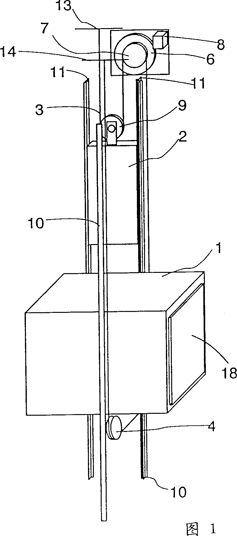
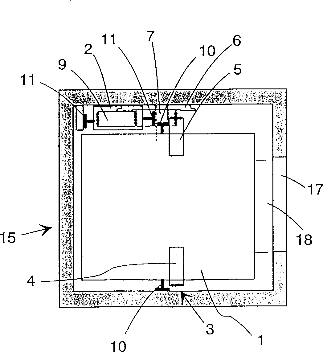
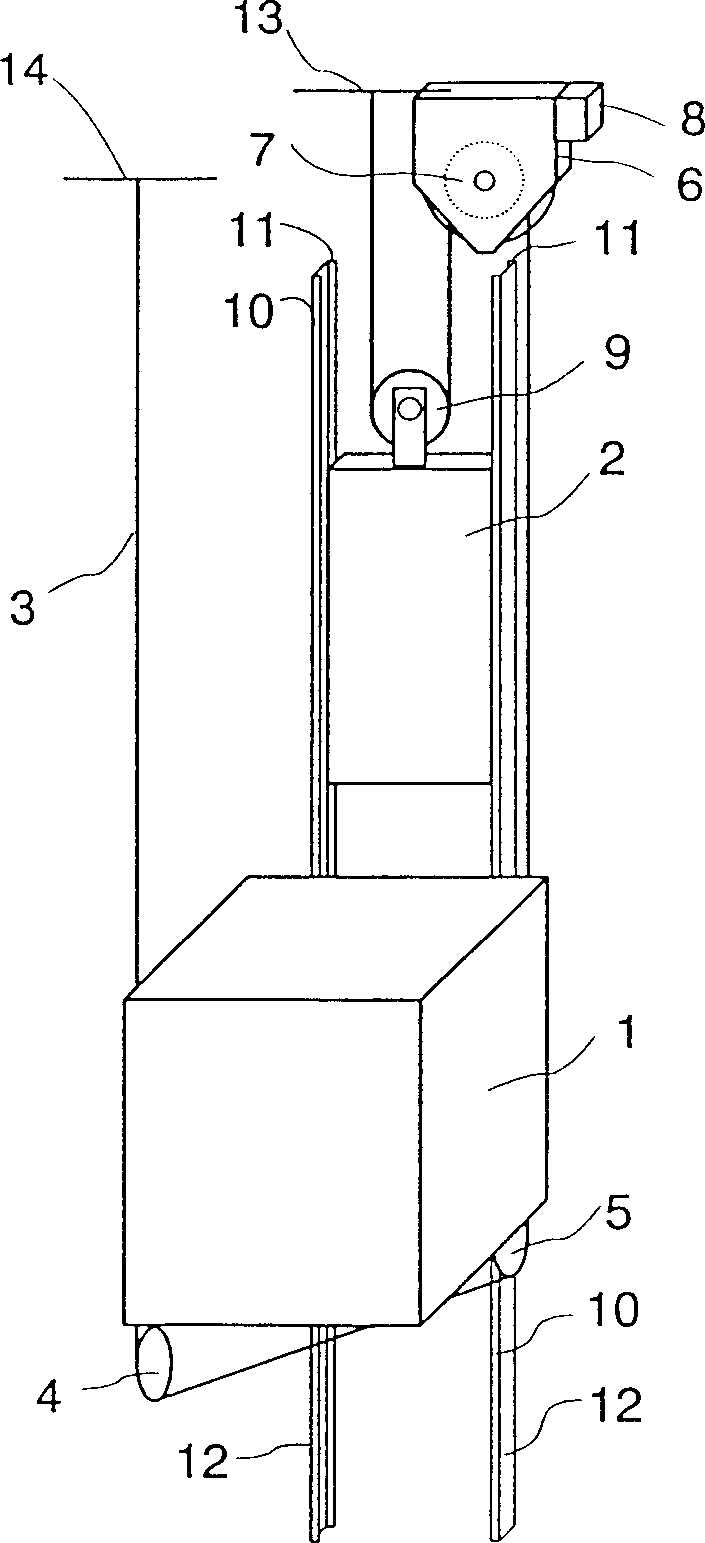
[0028] The schematic diagram of the traction sheave elevator of the present invention is shown in Figure 1. The car 1 and the counterweight 2 are suspended on the elevator hoisting rope 3. The hoisting rope 3 preferably supports the car 1 substantially centrally or symmetrically to a vertical line passing through the center of gravity of the elevator car 1. Similarly, the suspension of the counterweight 2 is also preferably substantially centered or symmetrical to the vertical line passing through the center of gravity of the counterweight. In FIG. 1, the car 1 is supported by the hoisting rope 3 through the diverting pulleys 4 and 5 with rope grooves, and the counterweight 2 is supported by the grooved diverting pulley 9. The steering pulleys 4 and 5 preferably rotate in substantially the same plane. Lifting rope 3 usually consists of several strands arranged side by side, generally at least 3 strands. The elevator driving device 6, with a traction sheave 7 engaged with the hoist...


PUM


Abstract

The invention relates to a traction sheave elevator, which comprises: a car (1) moving along the elevator guide rail (10), a counterweight (2) moving along the counterweight guide rail (11), supporting the car and the counterweight A heavy set of hoisting ropes (3), a driving device (6) comprising a traction rope gun (7), the traction sheave (7) driven by the driving device (6) and engaged with the hoisting ropes (3). The elevator drive (6) is located at the top of the elevator shaft (15), in the space between the shaft space required for the path of the car and/or its overhead extension and one wall of the elevator shaft.

Description

[0001] This application is a divisional application of an invention application whose filing date is 940628, application number is 94106597.9, and the title is called traction sheave elevator. technical field [0002] The invention relates to a traction sheave elevator and a driving device for the elevator. Background technique [0003] One of the goals in the development of elevators is the efficient and economical use of building space. In conventional elevators driven by traction sheaves, the elevator machine room or the elevator space reserved for the drive machinery accounts for a considerable portion of the building space required by the elevator. The issue is not just the amount of building space required to drive the machinery, but its location in the building. There are many solutions for setting up the computer room, but usually these greatly limit the building design, at least in terms of space utilization or appearance. For example, setting the computer room sp...

Claims


Application Information

Patent Timeline
IPC IPC(8): B66B11/08B66B7/00B66B7/06B66B7/08B66B9/00B66B11/00B66B11/04
CPCB66B11/002B66B11/0035B66B11/0045B66B11/008B66B11/0438B66B11/08
Inventor 埃斯科·奥兰科乔马·马斯特拉蒂哈里·哈科拉
Owner KONE CORP
Why Eureka
Try Eureka