Microscopic needle holder

A needle-holding pliers and pliers head technology, which is applied in the field of microsurgical wound suture in laryngology, can solve the problems of easy desoldering of welding points, short service life, unstable and unstable clamping needles, etc., and achieve a firm drive connection point , Reduce the difficulty of operation and save the cost of procurement

Inactive Publication Date: 2019-01-18
杭州科锐特医疗设备有限公司
View PDF1 Cites 1 Cited by
  • Summary
  • Abstract
  • Description
  • Claims
  • Application Information

AI Technical Summary

Problems solved by technology

[0002] The jaws of existing similar products are all horizontally toothed, and the jaws are connected to the driving rod by welding, which has disadvantages such as unstable and unstable clamping needles, easy desoldering of welding points, and short service life.

Method used


Image

  • Microscopic needle holder
  • Microscopic needle holder
  • Microscopic needle holder

Examples


Embodiment

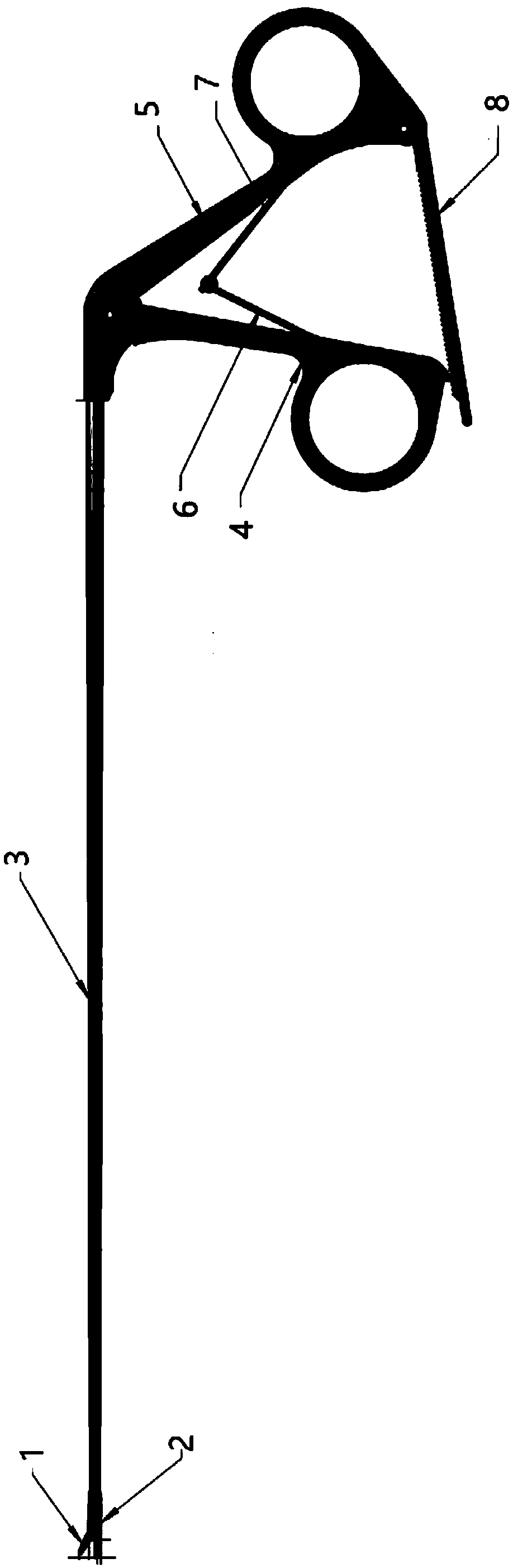
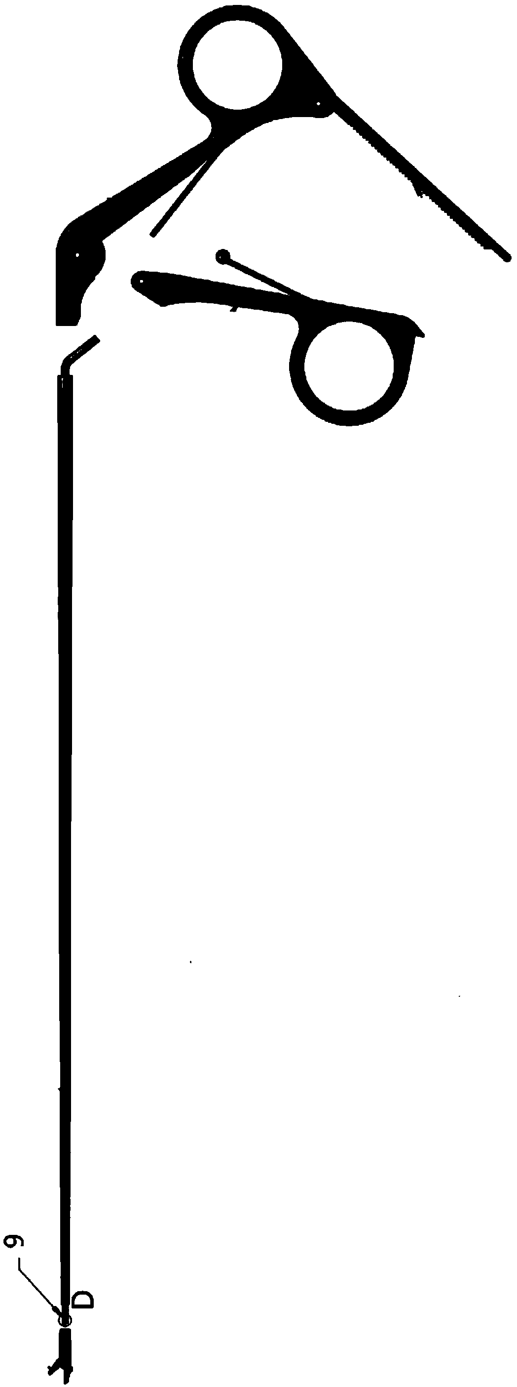
[0021] Embodiment: As shown in the accompanying drawings, this microscopic needle-holding forceps mainly includes an upper forceps head 1, a lower forceps head 2, a throat needle-holding forceps pipe 3, a front handle 4, a rear handle 5, a front spring leaf 6, a rear Spring leaf 7, lock buckle 8, drive rod 9, hole A91, cross pattern 12, horizontal pattern 21, upper clamp head 1 connects lower clamp head 2 and drive rod 9 and is installed on the front end of throat needle holder tube 3, drive rod 9 pass through the throat needle holder pipe 3 and be connected to the front handle 4, the front handle 4 is connected to the rear handle 5 installed at the rear end of the throat needle holder pipe 3, the front spring leaf 6 and the rear spring are connected between the rear handle 5 and the front handle 4 The spring leaf 7 is separated from each other, the rear handle 5 and the bottom of the front handle 4 are connected with the lock 8 to realize locking, the inner surface of the uppe...


PUM


Abstract

The invention discloses a microscopic needle holder, mainly including an upper tong head and a lower tong head. The inner side surface of the upper tong head is designed with cross reticulation. The inner side surface of the lower tong head is designed with transverse reticulation. The rear end of the upper tong head is provided with a vertical groove. The rear end of the upper tong head is also provided with a hole B. The front end of the driving rod is vertically flat and transversely perforated. The front end of the driving rod is inserted into the vertical groove of the rear end of the upper tong head and riveted with rivets. The surrounding gap is ground and leveled by laser welding. The needle holder reliably clamps the sewing needle, ensures the precision of sewing, reduces the operation difficulty of the doctor, and improves the operation quality. The driving connection point of the invention is firm, the failure rate is reduced, the service period is prolonged. User use cost is reduced. China has long relied on imported products for such fine instruments. And the needle holder can not only realize domestic substitution for import in response to the call of the state, but also save a large amount of procurement cost for the state.

Description

technical field [0001] The invention relates to the field of laryngology microsurgical wound suturing, in particular to a microneedle holding forceps. Background technique [0002] Existing products of the same kind have jaws with a horizontal tooth structure, and the jaws of the jaws are connected to the drive rod by welding, which has disadvantages such as unstable and unstable clamping of sewing needles, easy desoldering of welding points, and short service life. Contents of the invention [0003] The purpose of the present invention is to overcome the deficiencies in the prior art, and to provide a microscopic needle holder. [0004] The purpose of the present invention is accomplished through the following technical solutions: the microscopic needle-holding forceps mainly includes an upper forceps head, a lower forceps head, a throat needle-holding forceps tube, a front handle, a rear handle, a front spring leaf, and a rear spring leaf , lock, drive rod, hole A, cros...

Claims


Application Information

Patent Timeline
Patent Type & Authority Applications(China)
IPC IPC(8): A61B17/062
CPCA61B17/062
Inventor 刘建国
Owner 杭州科锐特医疗设备有限公司
Why Eureka
Try Eureka