
Stirring structure for production

A technology of agitating shaft and agitator, which is applied to mixer accessories, dissolving, mixers, etc., can solve problems such as excessive heat accumulation of server chassis during server working cycle, spontaneous combustion of server, and difficulty in maintaining the upper wall of server chassis.

Inactive Publication Date: 2019-01-18
NANJING INST OF RAILWAY TECH
View PDF1 Cites 0 Cited by
  • Summary
  • Abstract
  • Description
  • Claims
  • Application Information

AI Technical Summary

Problems solved by technology

[0012] In order to solve the above-mentioned problems, the present invention provides a stirring structure for production, which effectively avoids the problem of loosening and unreliability of the socket connector in the prior art, and the excessive duty cycle of the server in the server case makes the server case The heat accumulation of too much heat will cause the server to ignite spontaneously, and the vertical span of the server case is too large, making it difficult for the maintainer to maintain the upper wall of the server case

Method used


Image

  • Stirring structure for production
  • Stirring structure for production
  • Stirring structure for production

Examples


Embodiment 1

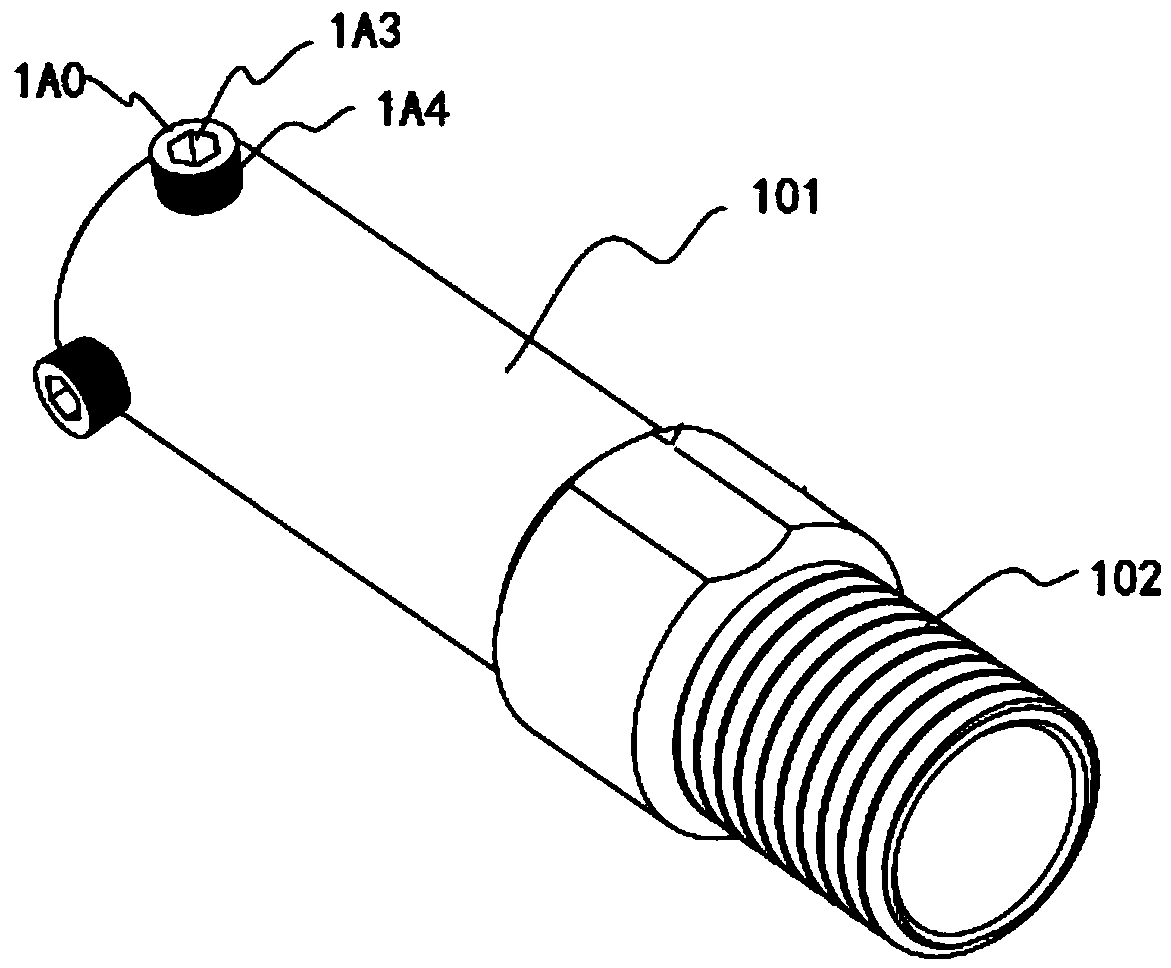
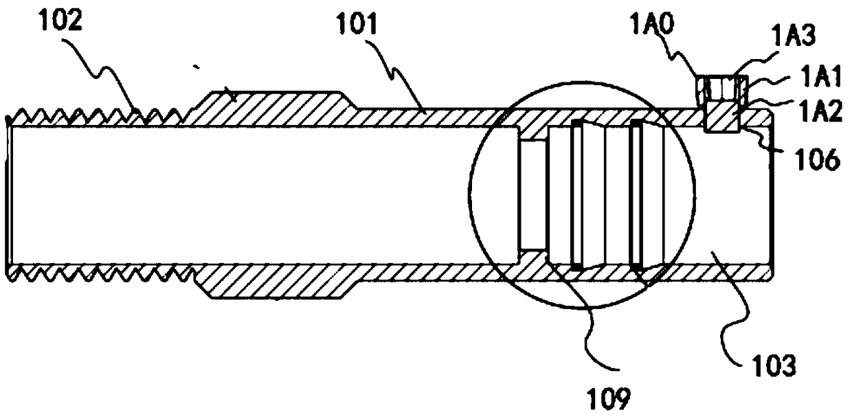
[0044] Such as Figure 1-Figure 5 As shown, the stirring structure for production includes the low-speed stirring device for paint production as described in the application number "201721437981.1", the application date is "2018.07.12" and the patent name is "a low-speed stirring device for paint production";

[0045] The low-speed stirring device for coating production includes a stirrer, a mixing bucket, and a fixed support. The stirrer includes a low-speed motor, a stirring shaft, and a stirring blade. The top of the stirring shaft is connected to the low-speed motor. The stirring blade is connected, the stirring shaft is installed inside the mixing barrel; the fixing bracket is arranged at the lower part of the mixing barrel, and both sides of the fixing bracket are provided with fixing plates, and the fixing plates There is a fixed hole on the top, the bottom of the mixing tank is provided with a discharge port, the top of the mixing tank is provided with a feeding port, ...

Embodiment 2

[0054] Such as Figure 1-Figure 5 As shown, the stirring structure for production includes the low-speed stirring device for paint production as described in the application number "201721437981.1", the application date is "2018.07.12" and the patent name is "a low-speed stirring device for paint production";

[0055] The low-speed stirring device for coating production includes a stirrer, a mixing bucket, and a fixed support. The stirrer includes a low-speed motor, a stirring shaft, and a stirring blade. The top of the stirring shaft is connected to the low-speed motor. The stirring blade is connected, the stirring shaft is installed inside the mixing barrel; the fixing bracket is arranged at the lower part of the mixing barrel, and both sides of the fixing bracket are provided with fixing plates, and the fixing plates There is a fixed hole on the top, the bottom of the mixing tank is provided with a discharge port, the top of the mixing tank is provided with a feeding port, ...


PUM


Abstract

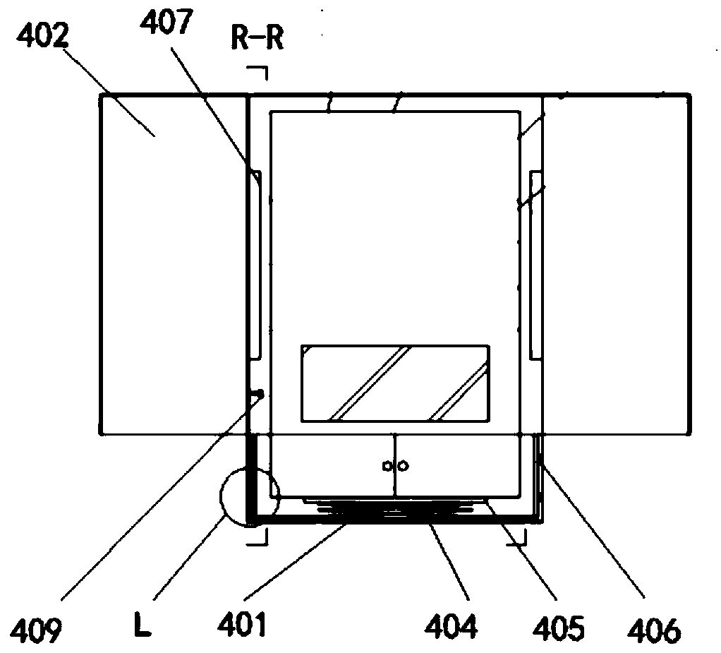
The invention discloses a stirring structure for production. A structure of connecting the top of a stirring shaft to a low-speed motor is that the stirring shaft is of a cylindrical structure, wherein an output shaft of the low-speed motor is also of a cylindrical structure; one end of the stirring shaft is connected with one end of the output shaft of the low-speed motor through a shaft connector; a server case comprises a case body, case doors, a strip-shaped opening I, a telescopic frame for vertically extending and retracting, a supporting table, a sheet shaped bulge I, a gas exhaust fan,a gas flow channel, a temperature display instrument and an anti-impact layer; two sides of the case body are provided with the case doors; the strip-shaped opening I is formed in the bottom of the case body. The stirring structure effectively avoids the problem that a shaft connector in the prior art is easily loosened and is not firm as a result of sleeve connection, and avoids the defects thatthe server spontaneously combusts as a result of too much gathered heat in the server case if the working period of the server in the server case is too long, and that a maintainer difficultly maintains the upper wall surface of the server case as the vertical span of the server case is too great.

Description

technical field [0001] The invention relates to the technical field of motor stirring, in particular to a stirring structure for production. Background technique [0002] During the construction process, in order to prevent the layering of the coating and make the components of the coating evenly distributed, it is necessary to adopt the method of stirring. The low-speed motor speed of some stirring devices is too high, the production process is complicated, the cost is high, and the noise is large, which is not conducive to the uniform mixing of the coating components. However, the current low-speed stirring has reduced efficiency and cannot achieve the best of both worlds. [0003] Therefore, a low-speed stirring device for paint production with the application number "201721437981.1", the application date of "2018.07.12" and the patent name "a low-speed stirring device for paint production" was introduced. [0004] The low-speed stirring device for coating production in...

Claims


Application Information

Patent Timeline
IPC IPC(8): B01F15/00
CPCB01F35/322B01F35/3204
Inventor 宋奇吼冯洪高陈莉周昌松徐百钏王帅徐媛媛王雪钰
Owner NANJING INST OF RAILWAY TECH
Learn More