Flow mixer device
A technology for mixers and equipment, applied in mixer accessories, mixers, dissolving and other directions, can solve the problems of loose combination, difficulty in assembly by staff, and cumbersome assembly of shaft connectors.
- Summary
- Abstract
- Description
- Claims
- Application Information
AI Technical Summary
Problems solved by technology
Method used
Image
Examples
Embodiment 1
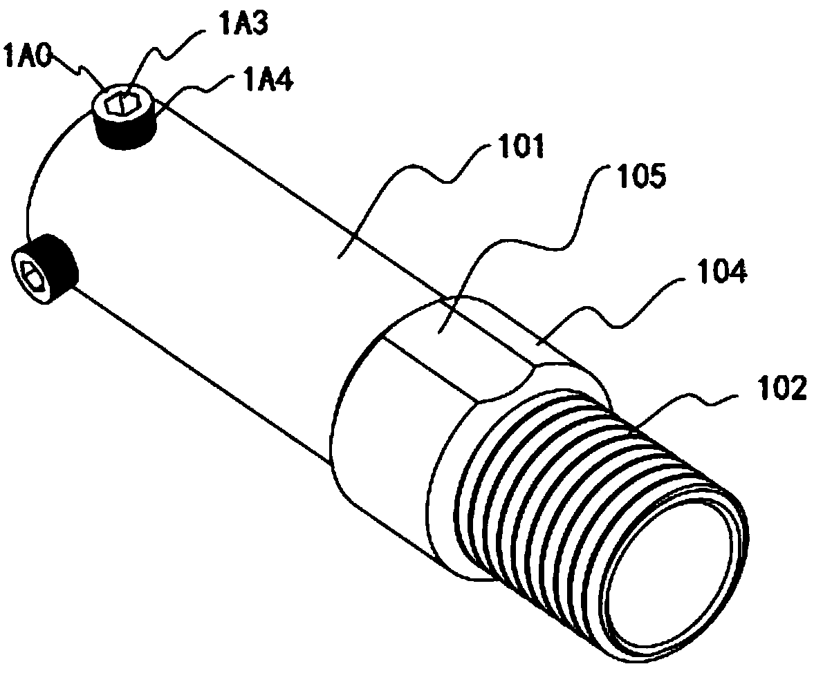
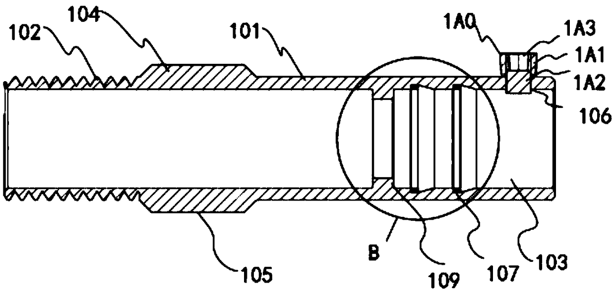
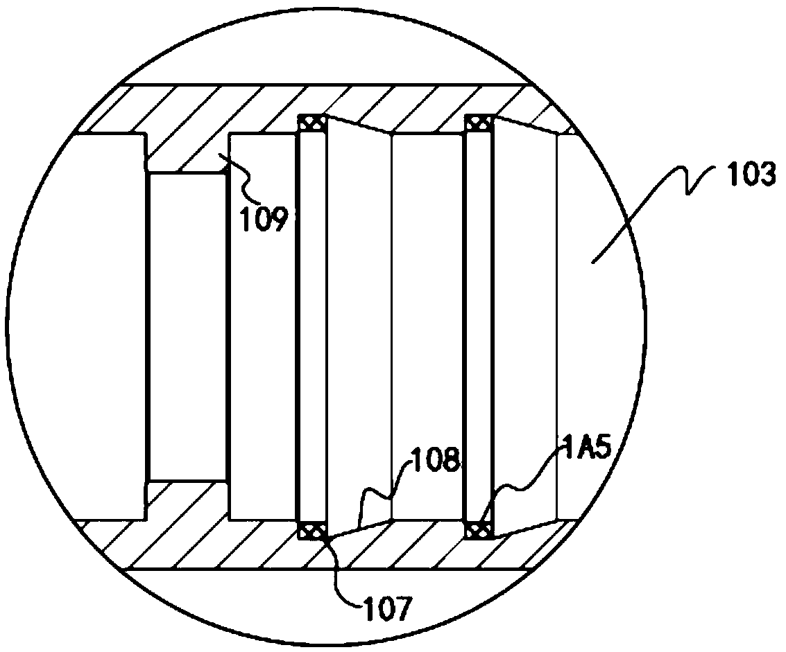
[0049] like Figure 1-Figure 6 As shown, the flow mixer equipment includes the filter type flow mixer as described in the application number "201721563745.4", the application date is "2018.06.15" and the patent name is "a filter type flow mixer";
[0050] The filter type flow mixer includes an equipment base, a stirring box and a fixing frame are arranged on the equipment base, a supporting plate is arranged on the upper end of the fixing frame, a crushing box is arranged on the supporting plate, and the Drive shafts are provided on the opposite sides of the crushing box, and a grinding wheel is set on the drive shaft. A drive motor is provided at one end of the drive shaft, and a filter screen A is provided in the crushing box and below the drive motor. A conveying pipeline is connected between the lower end of the side surface of the crushing box and the mixing box, and an auger conveyor is arranged in the conveying pipeline, and a filter B is arranged in the connecting plac...
Embodiment 2
[0057] like Figure 1-Figure 6 As shown, the flow mixer equipment includes the filter type flow mixer as described in the application number "201721563745.4", the application date is "2018.06.15" and the patent name is "a filter type flow mixer";
[0058] The filter type flow mixer includes an equipment base, a stirring box and a fixing frame are arranged on the equipment base, a supporting plate is arranged on the upper end of the fixing frame, a crushing box is arranged on the supporting plate, and the Drive shafts are provided on the opposite sides of the crushing box, and a grinding wheel is set on the drive shaft. A drive motor is provided at one end of the drive shaft, and a filter screen A is provided in the crushing box and below the drive motor. A conveying pipeline is connected between the lower end of the side surface of the crushing box and the mixing box, and an auger conveyor is arranged in the conveying pipeline, and a filter B is arranged in the connecting plac...
PUM
 Abstract
Description
Claims
Application Information
 - R&D Engineer
- R&D Manager
- IP Professional
- Industry Leading Data Capabilities
- Powerful AI technology
- Patent DNA Extraction
Browse by: Latest US Patents, China's latest patents, Technical Efficacy Thesaurus, Application Domain, Technology Topic, Popular Technical Reports.
© 2024 PatSnap. All rights reserved.Legal|Privacy policy|Modern Slavery Act Transparency Statement|Sitemap|About US| Contact US: help@patsnap.com


