Light bar loading device and glue dispenser

A light bar and mounting board technology, which is applied to the device and coating of the surface coating liquid, which can solve the problems of poor adaptability and other problems

Inactive Publication Date: 2019-01-18
TCL KING ELECTRICAL APPLIANCES HUIZHOU
View PDF8 Cites 4 Cited by
  • Summary
  • Abstract
  • Description
  • Claims
  • Application Information

AI Technical Summary

Problems solved by technology

[0003] The main purpose of the present invention is to propose a lamp bar feeding

Method used


Image

  • Light bar loading device and glue dispenser
  • Light bar loading device and glue dispenser
  • Light bar loading device and glue dispenser

Examples


Example Embodiment

[0024] The technical solutions in the embodiments of the present invention will be clearly and completely described below in conjunction with the accompanying drawings in the embodiments of the present invention. Obviously, the described embodiments are only a part of the embodiments of the present invention, rather than all the embodiments. Based on the embodiments of the present invention, all other embodiments obtained by those of ordinary skill in the art without creative work shall fall within the protection scope of the present invention.

[0025] It should be noted that if there is a directional indication (such as up, down, left, right, front, back...) in the embodiment of the present invention, the directional indication is only used to explain that it is in a specific posture (as shown in the drawings). If the specific posture changes, the relative positional relationship, movement, etc. of the components below will also change the directional indication accordingly.

[0...


PUM


Abstract

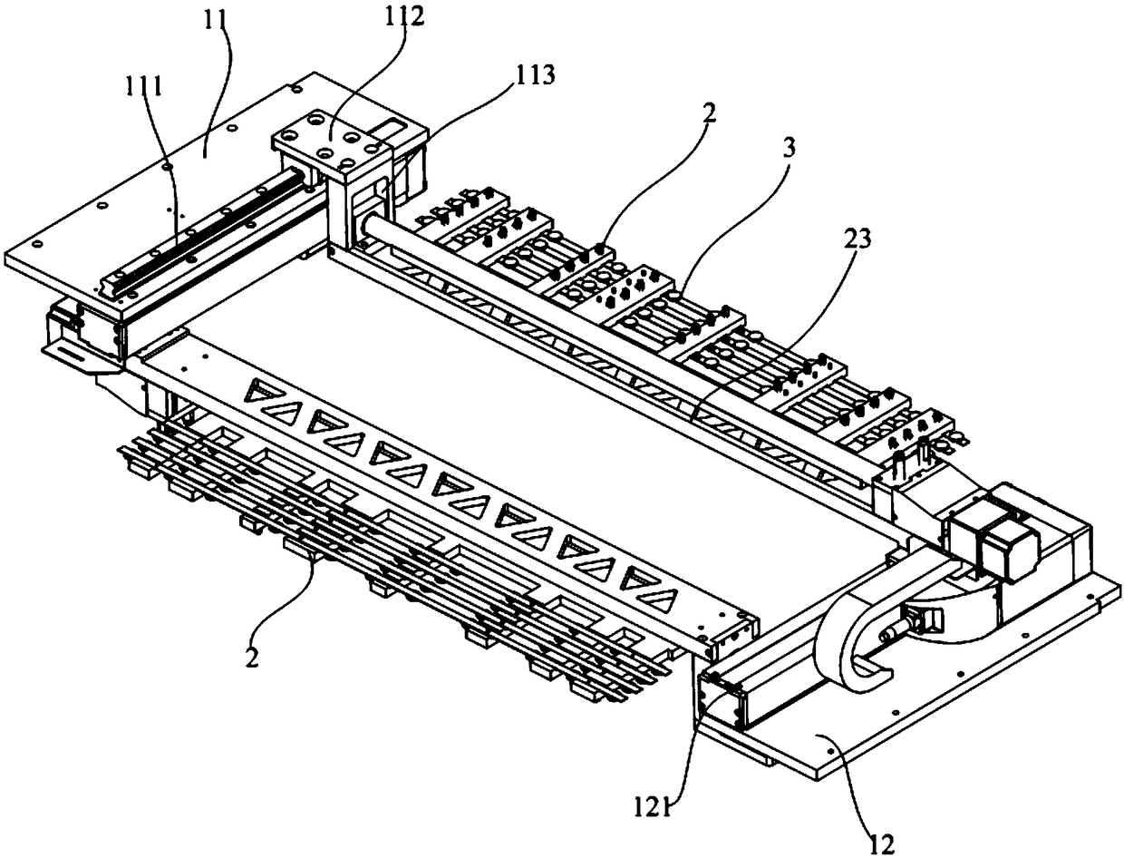
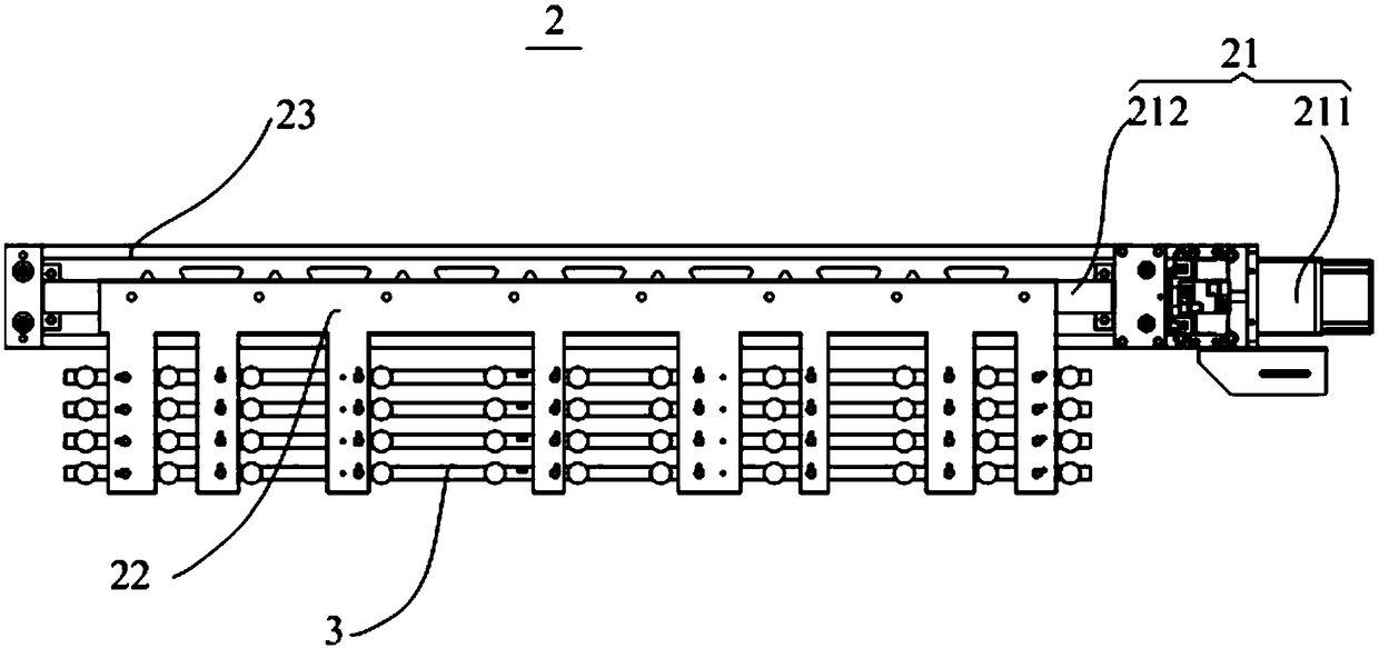
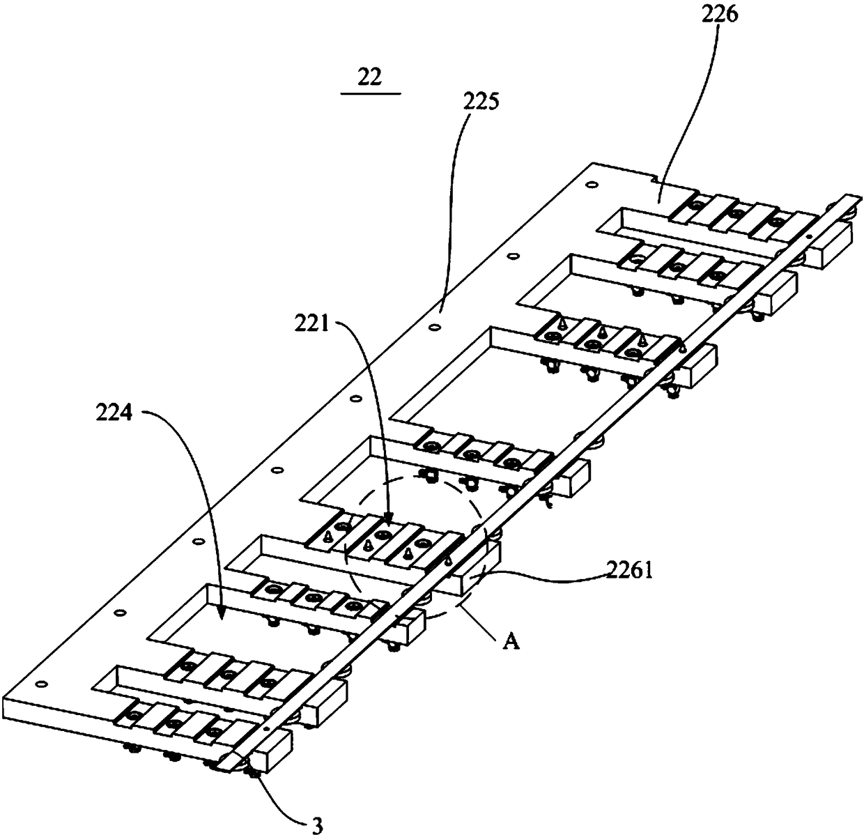
The invention discloses a light bar loading device and a glue dispenser. The light bar loading device comprises a mounting base, and at least one positioning part arranged on the mounting base, wherein the mounting base comprises a mounting plate and a positioning plate which are oppositely arranged; a slide rail and a slide base which is in sliding connection with the slide rail are arranged on the mounting plate; a drive module which corresponds to the slide rail is arranged on the positioning plate; one end of the positioning part is connected with the drive module; the other end of the positioning part can be in sliding connection with the mounting plate through the slide base; a vacuum sucking disc is arranged on the positioning part; and the vacuum sucking disc is used for adsorbinglight bars of various specifications. The light bar loading device sucks the light bars of various specifications through the vacuum sucking disc, so that the suitability of the device is improved.

Description

technical field [0001] The invention relates to the technical field of glue dispensing equipment, in particular to a light bar feeding device and a glue dispenser using the light bar feeding device. Background technique [0002] In the existing light bar dispensing equipment, a single feeding mechanism fixture is usually used to realize the feeding of a certain specification of light bars, for example: for light bars of various specifications from 32-inch light bars to 65-inch light bars, all It is necessary to produce light strip positioning fixtures corresponding to 32-inch light strips to 65-inch light strips; therefore, when light strips of different specifications need to be produced, different feeding mechanism fixtures need to be replaced, resulting in poor adaptability of the equipment. Problems, which in turn reduce the technical problems of the production efficiency of the equipment. Contents of the invention [0003] The main purpose of the present invention is...

Claims


Application Information

Patent Timeline
IPC IPC(8): B05C5/02B05C13/02
CPCB05C5/02B05C13/02
Inventor 郭国军
Owner TCL KING ELECTRICAL APPLIANCES HUIZHOU
Why Eureka
Try Eureka