Pressing-sleeve tool structure

A technology of tooling and indenters, applied in the field of aero-engine machinery manufacturing, can solve the problems of low processing efficiency, easy deflection and bending of punches, etc., and achieve the effect of good product quality and not easy to deflect

Inactive Publication Date: 2019-01-18
GUIZHOU HONGLIN MACHINERY
View PDF7 Cites 2 Cited by
  • Summary
  • Abstract
  • Description
  • Claims
  • Application Information

AI Technical Summary

Problems solved by technology

In the existing technology of pressing pins, most of the pins are pressed by hitting with a hammer. The defect of this processing method is that the impact force of hitting with a hammer is relatively large, and the punch is easy to be deflected. , the pin cannot be press-fitted in the vertical direction, which will cause the outer diameter of the pin to become larger (thicker or bent), which will directly affect product assembly and quality, low processing efficiency, and low pass rate
[0003] To sum up, the existing technology has a large impact force, the punch is easy to deflect, and the pin cannot be pressed in the vertical direction, which will cause the diameter of the outer circle of the pin to become larger, which will affect the product assembly and quality, and the processing efficiency is low. Low rate of technical issues

Method used


Image

  • Pressing-sleeve tool structure
  • Pressing-sleeve tool structure
  • Pressing-sleeve tool structure

Examples


Embodiment Construction

[0023] The present invention will be further described below in conjunction with the accompanying drawings and embodiments, but not as a basis for limiting the present invention.

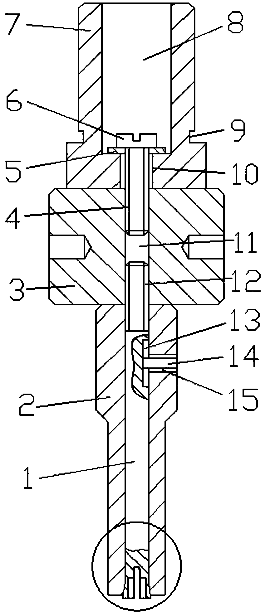
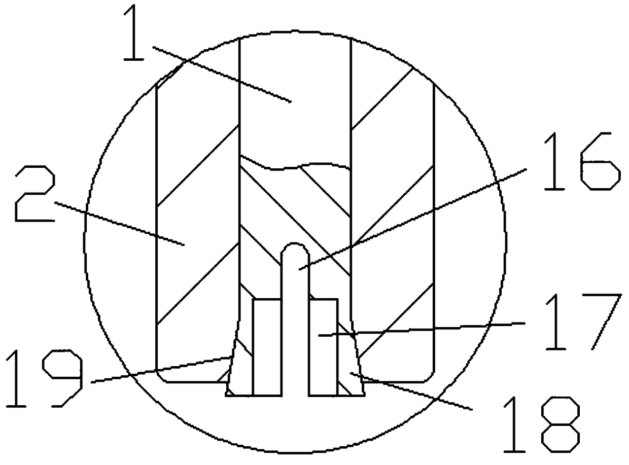
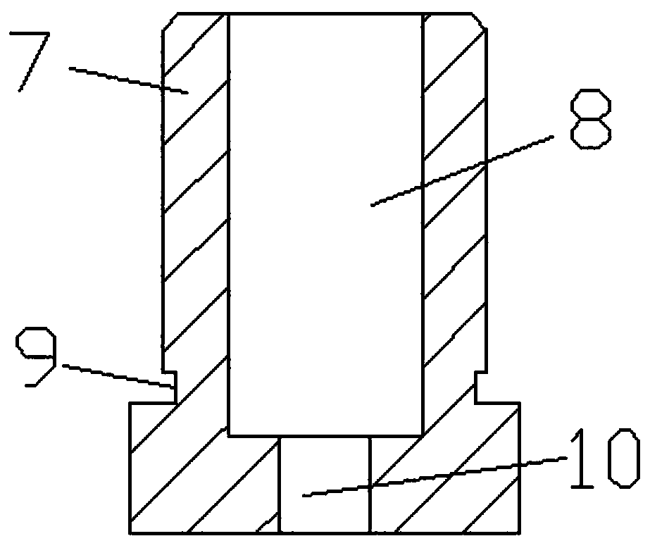
[0024] Example. A press sleeve tooling structure, constituted as Figure 1-9 As shown, there is a pressure head 7, the bottom of the pressure head 7 is provided with a nut 3, the axis of the nut 3 is vertically provided with a threaded hole 11, and the bottom of the nut 3 is provided with a sleeve 2; Fixed hole 8 is arranged, and the pressure head 7 of fixed hole 8 lower ends is provided with connecting hole 10, is provided with screw 6 movablely in connecting hole 10, and the lower end of screw 6 is connected with the threaded hole 11 of nut 3 upper end through first screw thread 4; The inner cylinder of the sleeve 2 is movable with a pull rod 1, the upper end of the pull rod 1 is movably connected with the threaded hole 11 at the lower end of the nut 3 through the second thread 12, and the pull r...


PUM


Abstract

The invention discloses a pressing-sleeve tool structure. The pressing-sleeve tool structure comprises a pressing head, a nut is arranged below the pressing head, a threaded hole is vertically formedin shaft center of the nut, and a sleeve is arranged below the nut; a fixing hole is formed in the upper end of the pressing head, a connecting hole is formed in the pressing head at the lower end ofthe fixing hole, a screw is movably arranged in the connecting hole, and a threaded hole formed in the upper end of the nut is connected to the lower end of the screw through a first thread; a pullingrod is movably arranged in an inner cylinder of the sleeve, a threaded hole formed in the lower end of the nut is movably connected to the upper end of the pulling rod through a second thread, a strip-type limiting groove is vertically formed in the pulling rod, a limiting threaded hole is formed in the sleeve on one side of the strip-type limiting groove, and an adjusting screw is movably connected to the limiting threaded hole through a thread. The pressing-sleeve tool structure has the advantages that static-pressure press fitting is achieved, a punching head is not prone to deflection, apin can be subjected to press fitting in the perpendicular direction, it can be avoided that the external-circle diameter of the pin can be increased, it is avoided that assembling of a product is influenced, the product quality is good, the machining efficiency is high, and the percent of pass is high.

Description

technical field [0001] The invention relates to all kinds of products (military products, civilian products and foreign trade products, etc.) that need to press sleeve (pin) assemblies, especially the press sleeve (pin) assemblies of assemblies in the field of aero-engine machinery manufacturing. Background technique [0002] At present, in mechanical manufacturing, many product assemblies require press-fitting pins, which puts forward higher demands on pin press-fitting technology. In the existing technology of pressing pins, most of the pins are pressed by hitting with a hammer. The defect of this processing method is that the impact force of hitting with a hammer is relatively large, and the punch is easy to be deflected. , the pin cannot be press-fitted in the vertical direction, which will cause the diameter of the outer circle of the pin to become larger (thick or bent), directly affecting product assembly and quality, low processing efficiency, and low pass rate. [...

Claims


Application Information

Patent Timeline
Patent Type & Authority Applications(China)
IPC IPC(8): B25B27/02
CPCB25B27/02
Inventor 韦芬周可平何林美袁涛
Owner GUIZHOU HONGLIN MACHINERY
Why Eureka
Try Eureka