Automated metal piece machining device

A processing device and a technology for metal parts, applied in the field of metal parts processing, can solve the problems of time-consuming and cutting efficiency reduction, etc.

Inactive Publication Date: 2019-01-18
镇江倍斯特曼新材料研究有限公司
View PDF0 Cites 2 Cited by
  • Summary
  • Abstract
  • Description
  • Claims
  • Application Information

AI Technical Summary

Problems solved by technology

[0003] However, large-scale pipe fittings often need to be transported by hoisting after cutting, and the position of the blank pipe often needs to be locked when cutting, and repeated clamping takes man-hours, resulting in a decrease in cutting efficiency

Method used


Image

  • Automated metal piece machining device
  • Automated metal piece machining device
  • Automated metal piece machining device

Examples


Embodiment Construction

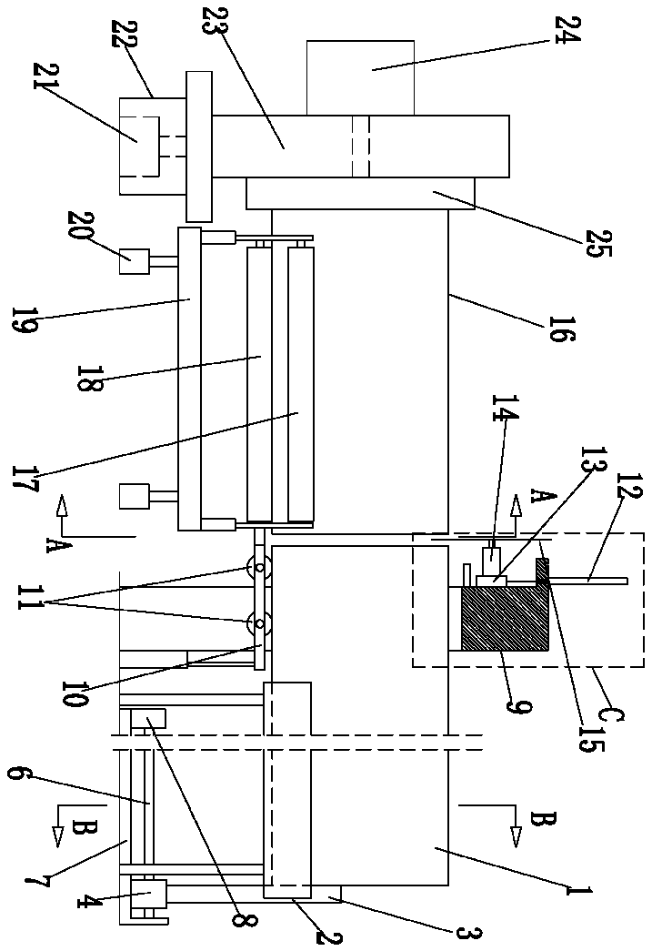
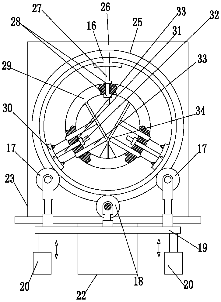
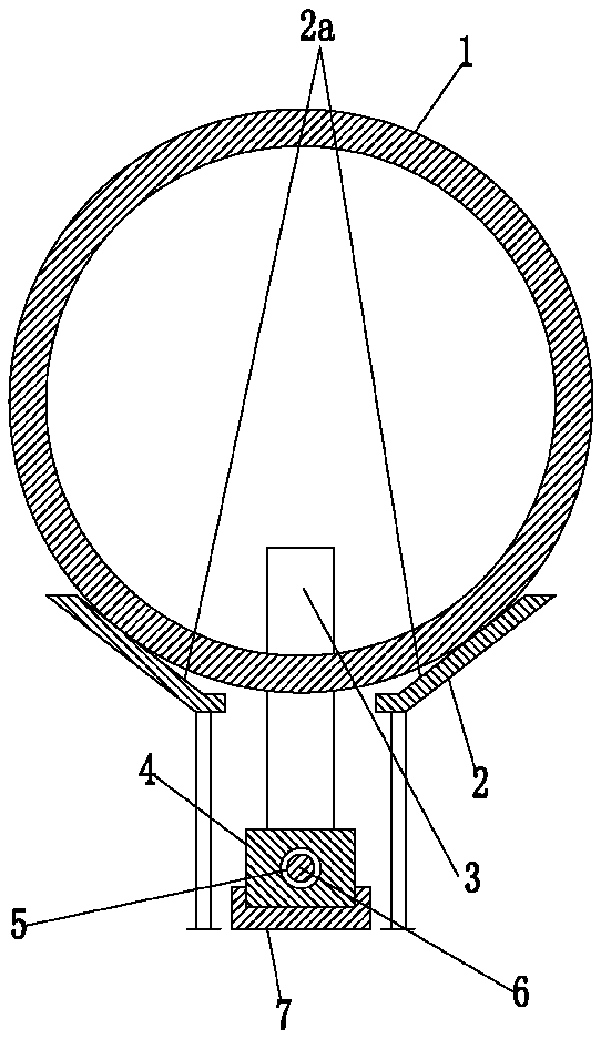
[0020] like Figure 1-6 As shown, an automatic metal parts processing device includes a conveying part for conveying the blank tube 1, a cutting part for cutting the blank tube 1, a transfer part for transferring the cut finished tube 16, and It includes a PLC controller 35, and the conveying parts, cutting parts, and transfer parts are arranged sequentially according to the conveying process, and the conveying parts include a pair of side brackets 2 that are spaced from each other and set opposite to each other, and whose extension direction is consistent with the conveying direction of the blank tube 1, The opposite sides of the two side brackets 2 are provided with inclined side bracket slopes 2a for supporting the outer peripheral wall of the blank tube 1, and the conveying part also includes a magnetic support for abutting against the non-cut side shaft end of the blank tube 1. The magnetic abutment bar 3 also includes a feed linear drive mechanism installed on the ground...


PUM


Abstract

The invention discloses an automated metal piece machining device. The device includes a conveying assembly used for conveying blank pipes, a cutting assembly used for cutting the blank pipes, a transferring assembly used for transferring cut finished pipe products and a PLC. The conveying assembly, the cutting assembly and the transferring assembly are distributed sequentially according to a conveying flow; the conveying assembly includes a pair of lateral support bases which are oppositely arranged at an interval, and the extension directions of the lateral support bases are identical to theconveying direction of the blank pipes. The conveying assembly also includes a magnetic butting strip and a linear feeding driving mechanism, the magnetic butting strip is used for butting against the axial ends of non-cutting sides of the blank pipes and has magnetism, the linear feeding driving mechanism is used for driving the magnetic butting strip to horizontally move and mounted on the ground, a gap penetrable for the magnetic butting strip during movement is formed between the two lateral support bases, and the length direction of the gap is identical to the conveying direction of theblank pipes. The automated metal piece machining device provides convenience for transferring and locking the finished pipe products.

Description

technical field [0001] The invention relates to the technical field of metal processing, in particular to a processing device for cutting large pipes. Background technique [0002] Large-scale pipe fittings are often used to transport fluid media or manufacture large-scale bearing parts, etc. Therefore, when cutting large-scale pipe fittings, it is necessary to use special equipment for operations. The pipe cutting part also includes a transfer part for transferring the cut finished pipe, and also includes a PLC controller, and the conveying part, the cutting part and the transfer part are arranged in sequence according to the conveying process. [0003] However, large-scale pipe fittings often need to be transported by hoisting after cutting, and the position of the blank pipe often needs to be locked when cutting. Repeated clamping consumes man-hours, resulting in a decrease in cutting efficiency. Contents of the invention [0004] The purpose of the present invention i...

Claims


Application Information

Patent Timeline
Patent Type & Authority Applications(China)
IPC IPC(8): B26D1/18B26D7/02B26D7/06
CPCB26D1/18B26D7/02B26D7/0608B26D2007/013
Inventor 袁潘臣
Owner 镇江倍斯特曼新材料研究有限公司
Why Eureka
Try Eureka