
A thermos bottle liner conveying and dumping device

A technology of pouring device and thermos bottle, which is applied in the direction of conveyor, transportation and packaging, conveyor objects, etc., which can solve the problems of waste of manpower, insufficient function and simplicity.

Active Publication Date: 2020-04-21
蚌埠市嘉舜日用品有限公司
View PDF8 Cites 0 Cited by
  • Summary
  • Abstract
  • Description
  • Claims
  • Application Information

AI Technical Summary

Problems solved by technology

In the production process of the thermos liner, it is necessary to clean the liner of the thermos bottle, but the existing cleaning device mechanism is too simple, which leads to insufficient functions, and cannot automatically clean the liner of the thermos bottle during the transportation process after the liner is cleaned. Sewage is dumped, discharged, recycled, filtered, and recycled, which wastes a lot of manpower. The invention provides a thermos bottle liner conveying and dumping device

Method used


Image

  • A thermos bottle liner conveying and dumping device
  • A thermos bottle liner conveying and dumping device
  • A thermos bottle liner conveying and dumping device

Examples


Embodiment 1

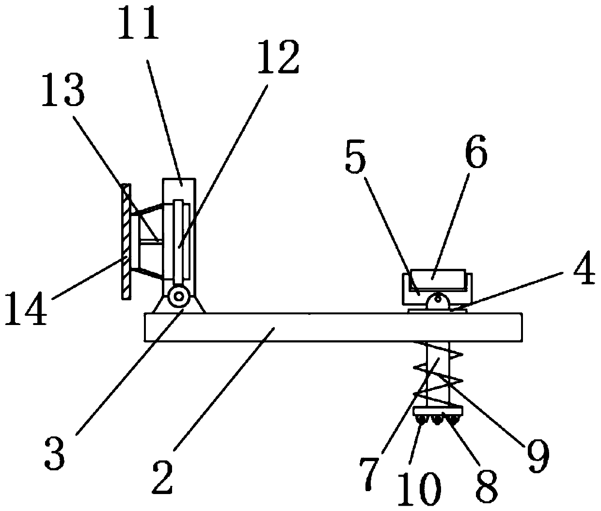
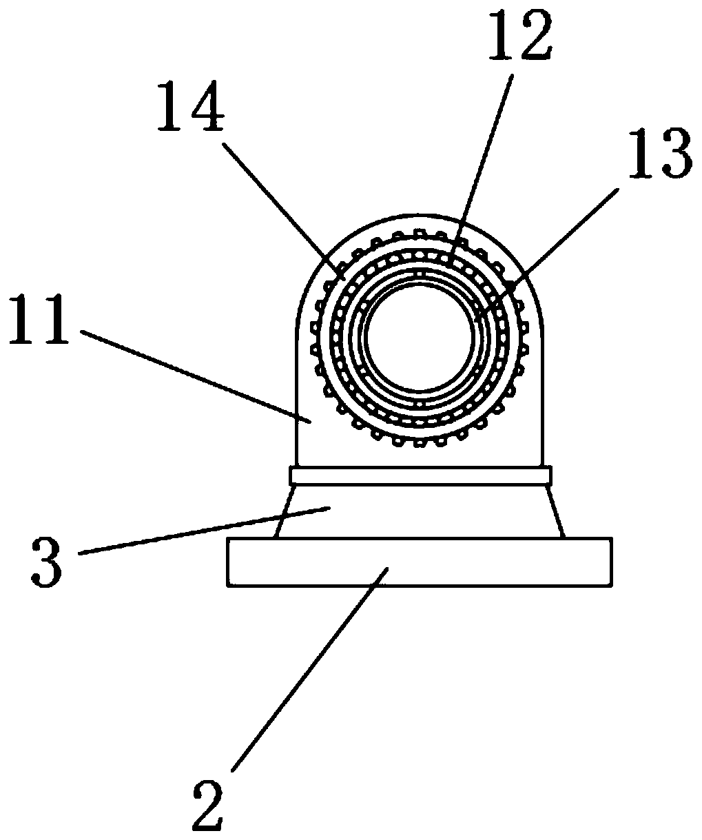
[0034] Embodiment 1: as Figure 1-13As shown, a thermos bottle liner conveying and dumping device includes a conveyor 1 and a chain plate 2, four sets of legs 55 are fixedly connected to the bottom of the conveyor 1, and several supporting wheels 54 are fixedly installed on the top of the conveyor 1 , the top and bottom of the conveyor 1 are provided with concave cavities 53, the top left side of the chain plate 2 is fixedly connected with a first base 3, and the top of the first base 3 is rotatably connected with a fixed frame 11 , the inner wall of the fixed frame 11 is fixedly equipped with a bearing 12, the inner wall of the bearing 12 is fixedly connected with a casing 13, the left side of the casing 13 is fixedly connected with a ring gear 14, and the right side of the chain plate 2 A strut 7 is movably connected through, the top of the strut 7 is fixedly connected with a second base 4, the top of the second base 4 is rotatably connected with a bracket 5, and the top of ...

Embodiment 2

[0038] Embodiment 2: as Figure 1-14 As shown, a thermos bottle liner conveying and dumping device includes a conveyor 1 and a chain plate 2, four sets of legs 55 are fixedly connected to the bottom of the conveyor 1, and several supporting wheels 54 are fixedly installed on the top of the conveyor 1 , the top and bottom of the conveyor 1 are provided with concave cavities 53, the top left side of the chain plate 2 is fixedly connected with a first base 3, and the top of the first base 3 is rotatably connected with a fixed frame 11 , the inner wall of the fixed frame 11 is fixedly equipped with a bearing 12, the inner wall of the bearing 12 is fixedly connected with a casing 13, the left side of the casing 13 is fixedly connected with a ring gear 14, and the right side of the chain plate 2 A strut 7 is movably connected through, the top of the strut 7 is fixedly connected with a second base 4, the top of the second base 4 is rotatably connected with a bracket 5, and the top of...


PUM


Abstract

The invention discloses a vacuum flask lining delivery tipping device. The device comprises a delivery machine and a chain plate, a vacuum flask lining positioning mechanism is arranged on the chain plate, an automatic water adding device is fixedly mounted at the front side of the left end of the delivery machine, the left portion of the delivery machine is provided with a self-cleaning section,the right portion of the delivery machine is provided with a tipping section, a water tank is fixedly connected with the front side of the right section of the delivery machine, a filtering device isfixedly installed at the bottom of the water tank, and an automatic discharging device is fixedly installed on the front side of the right end of the delivery machine. By means of the device, automatic cleaning of the inner cavity of the vacuum flask lining can be achieved to greatly liberate production labor force, the cleaning effect is better, the working efficiency is improved, and the popularization and use of the device are convenient.

Description

Technical field: [0001] The invention relates to the field of machinery, in particular to a conveying and dumping device for a thermos bottle liner. Background technique: [0002] Vacuum bottle is also called thermos bottle. It is a kind of modal daily necessities. The bottle has an inner wall and an outer wall; there is a vacuum between the two walls. Heat conduction and convection cannot be carried out in a vacuum, and the metal reflective layer coated can reflect heat radiation. Therefore, any liquid poured into the bottle can maintain its original temperature for a long period of time. That's why thermoses keep drinks warm in winter and cold in summer. In the production process of the thermos liner, it is necessary to clean the liner of the thermos bottle, but the existing cleaning device mechanism is too simple, which leads to insufficient functions, and cannot automatically clean the liner of the thermos bottle during the transportation process after the liner is cl...

Claims


Application Information

Patent Timeline
Patent Type & Authority Patents(China)
IPC IPC(8): B65G49/02B67C9/00B08B3/04
CPCB08B3/04B65G49/025B65G2201/0244B67C9/00
Inventor 姚争富柳冬冬
Owner 蚌埠市嘉舜日用品有限公司
Learn More