Vehicle for a magnetic levitation track

A transportation tool and magnetic levitation technology, which is applied in sliding/floating railway systems, transport passenger cars, transport passenger cars, etc., can solve the problems of suspension device structure cost, small mobility, etc., and achieve comfortable driving operation, good rigidity and driving effect

Active Publication Date: 2014-09-10
MAX BOGL BAUUNTERNEHMUNG
View PDF7 Cites 5 Cited by
  • Summary
  • Abstract
  • Description
  • Claims
  • Application Information

AI Technical Summary

Problems solved by technology

[0006] The known solution has the disadvantage that on the one hand the drive and support device has low mobility relative to the vehicle body, so that only lanes with a relatively large radius can be used and on the other hand the suspension device is very complex in construction. Structure

Method used


Image

  • Vehicle for a magnetic levitation track
  • Vehicle for a magnetic levitation track
  • Vehicle for a magnetic levitation track

Examples


Embodiment Construction

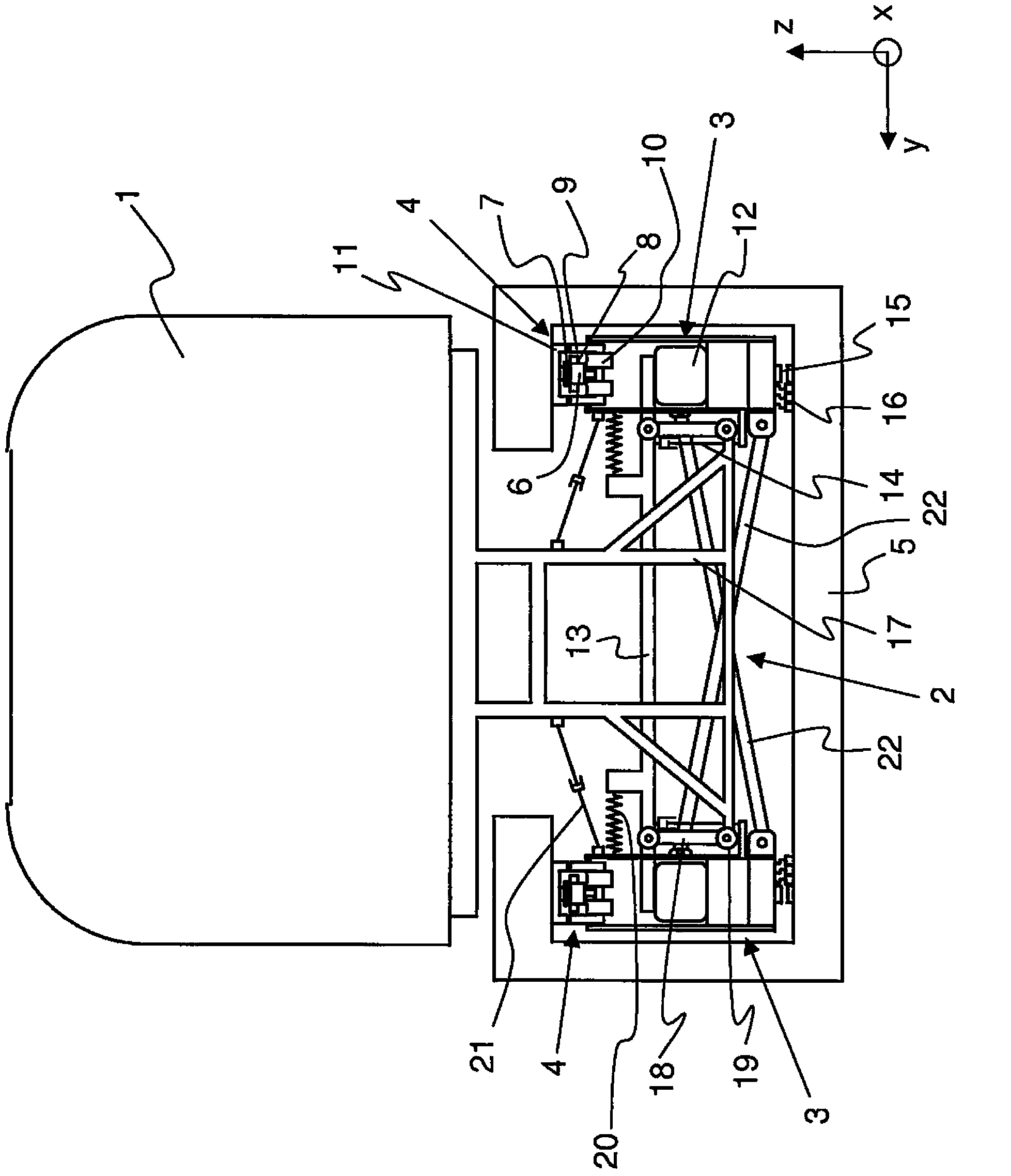
[0034] figure 1 shows a cross-sectional view through a vehicle for a maglev railway according to the invention, the vehicle having a car body 1, a suspension 2 and a plurality of modules 3 in which drive and support devices 4 are arranged . The vehicle is guided into a track beam 5 which surrounds modules 3 and suspensions 2 in a C-shape. The drive and support device 4 has a linear motor and a part of the support device. The linear motor here is a short stator linear motor with an iron core 6 and a reaction rail 7 . A winding 8 is embedded in the iron core 6 . The linear motor is surrounded by a U-shaped yoke 9 with a coil 10 connected thereto and a U-shaped reaction rail 11 . Two reaction rails 7 and 11 are fixed on the rail beam 5 . The iron core 6 , the winding 8 as well as the yoke 9 and the coil 10 are located on the vehicle or on the drive and support device 4 . The support device is used to attract the reaction rail 11 through the yoke 9 to make the vehicle in a s...


PUM


Abstract

The present invention relates to a vehicle for a magnetic levitation track having a coach body (1) and a propulsion and supporting device (4) as well as at least one levitation frame (2) fastened on the coach body (1) and the propulsion and supporting device (4). The levitation frame (2) can be deflected transversely to the longitudinal axis of the propulsion and supporting device (4) and a spring suspension system (12, 14, 20, 21) is arranged between the levitation frame (2) and propulsion and supporting device (4). The levitation frame (2) has a traverse (13) and a carrier (17) which are connected to each other in an articulated fashion.

Description

technical field [0001] The present invention relates to a vehicle for a maglev railway, which has a car body, a driving and supporting device, and at least one suspension fixed at the car body and the driving and supporting device, wherein the suspension is perpendicular to the The longitudinal axis of the drive and support device is rotatable and a spring-shock absorber system is arranged between the suspension and the drive and support device. Background technique [0002] Vehicles for maglev railways generally have a substantially rigid body on which a plurality of drive and support devices are fixed. The plurality of drive and support devices must follow the roadway and can therefore also follow a predetermined spatial curve corresponding to the radius of the roadway. Furthermore, the permissible clearance between the drive and support device of the vehicle and the roadway is very small, so that the drive and support device must be able to move relative to the vehicle b...

Claims


Application Information

Patent Timeline
Patent Type & Authority Applications(China)
IPC IPC(8): B60L13/10B61B13/08
CPCB60L13/10B61B13/08B61F1/00B60L13/08B61D1/00B60L13/04
Inventor 斯特凡·博格尔
Owner MAX BOGL BAUUNTERNEHMUNG
Why Eureka
Try Eureka