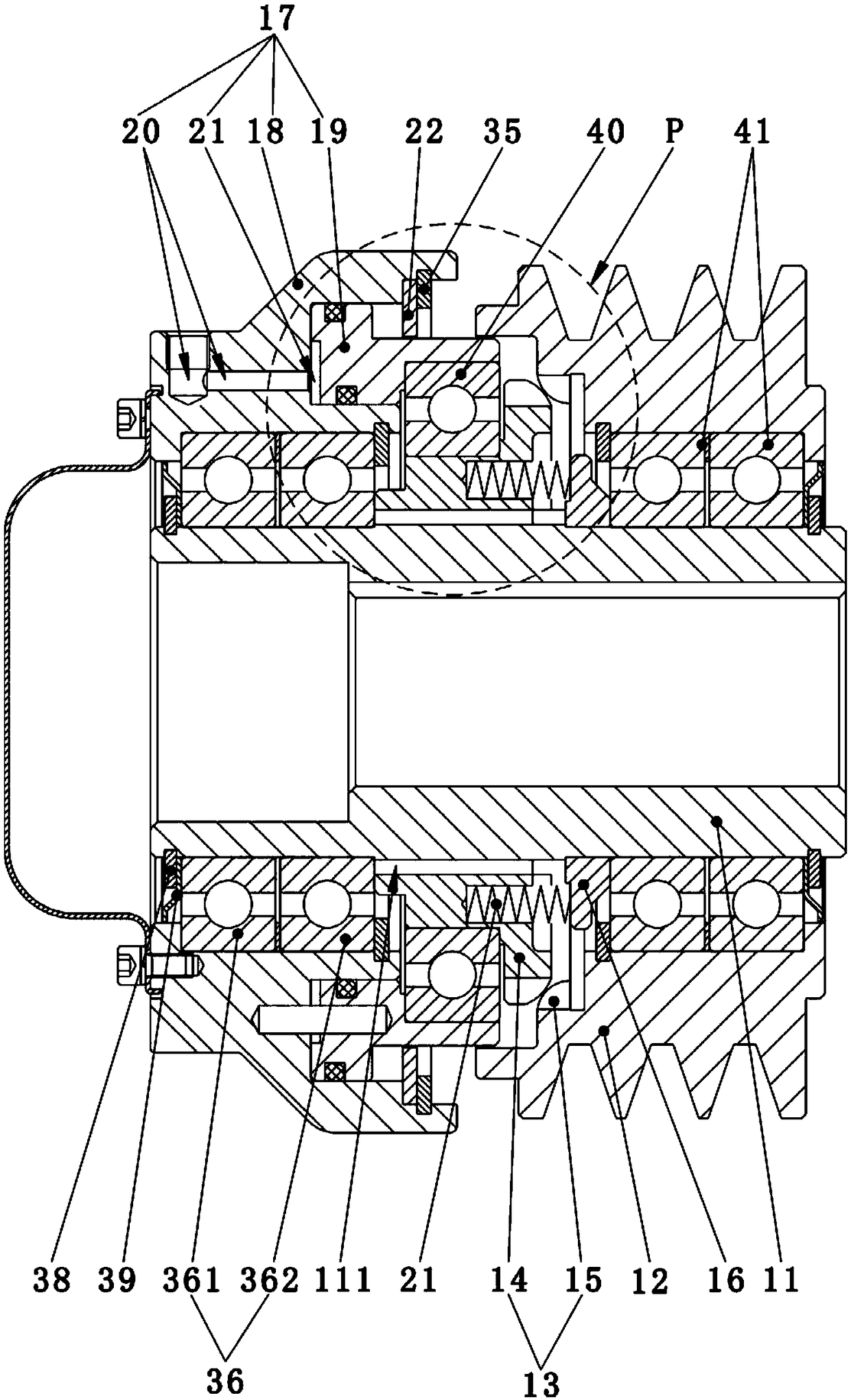
Clutch

A clutch and gear technology, applied in the field of clutches, can solve the problems affecting the service life of products, excessive travel, and excessive input air pressure, and achieve the effects of increasing service life, reducing area and reducing friction.

Pending Publication Date: 2019-01-18
XIAMEN SOUTH SUPER MACHINERY CO LTD
View PDF0 Cites 8 Cited by
  • Summary
  • Abstract
  • Description
  • Claims
  • Application Information

AI Technical Summary

Problems solved by technology

[0003] The purpose of the present invention is to solve the problem that the axial travel of the piston of the existing pneumatic tooth clutch is too large due to the large input air pressure, which affects the service life of the product

Method used


Image

  • Clutch
  • Clutch
  • Clutch

Examples


Embodiment Construction

[0034] In order to make the purpose, technical solutions and advantages of the embodiments of the present invention clearer, the technical solutions in the embodiments of the present invention will be clearly and completely described below in conjunction with the accompanying drawings in the embodiments of the present invention. Obviously, the described embodiments It is some embodiments of the present invention, but not all of them. Based on the implementation manners in the present invention, all other implementation manners obtained by persons of ordinary skill in the art without creative efforts fall within the protection scope of the present invention. Accordingly, the following detailed description of the embodiments of the invention provided in the accompanying drawings is not intended to limit the scope of the claimed invention, but merely represents selected embodiments of the invention.

[0035] In describing the present invention, it should be understood that the te...


PUM


Abstract

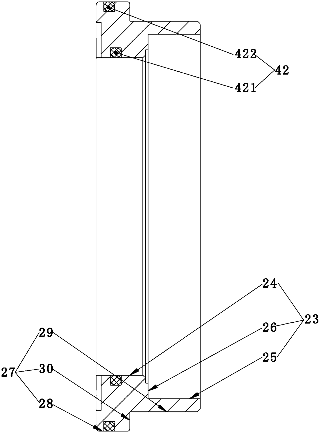
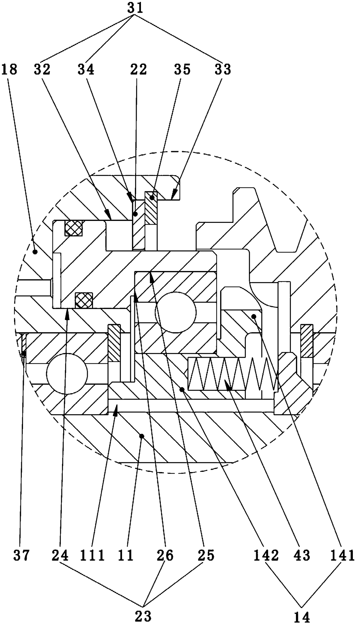
The invention relates to a clutch. The clutch comprises a first rotor, a second rotor, a clutch mechanism, an air cylinder mechanism and an elastic assembly; the second rotor fixedly sleeves the firstrotor through a first bearing assembly; the clutch mechanism is provided with a first gear piece which is arranged on the first rotor and can rotate along with the first rotor and a second gear piecewhich is arranged on the second rotor and can rotate along with the second rotor. The air cylinder mechanism comprises a shell and a piston piece cooperating with the shell to form with an air cavity. The elastic assembly is provided with an elastic piece, and the elastic piece can push the first gear piece to get away from the second gear piece during resetting. The first gear piece is meshed with the second gear piece when a piston axially moves for a first predetermined distance. The clutch further comprises a stroke limiting piece for limiting the piston piece to axially move for a distance exceeding a second predetermined distance. The stroke of the piston piece is limited by the stroke limiting piece, the acting force borne by the elastic piece can be limited and stabilized, the counter-acting force borne by bearings connected with the elastic piece and other parts is limited and stabilized, and the service life of the other parts and the bearings is prolonged.

Description

technical field [0001] The invention belongs to the technical field of clutches, in particular to a clutch. Background technique [0002] The existing pneumatic tooth clutch structure is a fine-toothed pneumatic clutch. combine Figure 5 , The existing pneumatic tooth clutch includes a first rotor A, a second rotor B disposed on the first rotor A through a bearing, a clutch mechanism C, a cylinder mechanism D and an elastic member E. The clutch mechanism C includes a first gear C1 sleeved on the first rotor A and capable of rotating therewith, and a second gear C2 integrally formed with the second rotor B. The cylinder mechanism consists of a housing D1 and a piston D2. When the piston D2 is pushed by the air pressure, it will continue to move axially from left to right, thereby pushing the first gear C1 and the second gear C2 to mesh, and then the first rotor A rotates. can drive the second rotor B to rotate. When the first gear member C1 approaches the second gear membe...

Claims


Application Information

Patent Timeline
Patent Type & Authority Applications(China)
IPC IPC(8): F16D25/063F16D25/12
CPCF16D25/063F16D25/12
Inventor 熊鹏生林剑荣陶欢王辉陈俊宏丘国强陈源陈淋杨銮罗振韬
Owner XIAMEN SOUTH SUPER MACHINERY CO LTD
Why Eureka
Try Eureka