Eureka AIR delivers breakthrough ideas for toughest innovation challenges, trusted by R&D personnel around the world.

Dual mass flywheel

A dual-mass flywheel and mass flywheel technology is applied to flywheels, springs/shock absorbers, vibration suppression adjustments, etc., which can solve problems such as the inability to achieve the best shock absorption effect, limited service life of springs, and limited contact area. Good vibration effect, good elasticity effect, long service life effect

Pending Publication Date: 2019-01-18
禹州市竹园机械制造有限公司
View PDF0 Cites 0 Cited by
  • Summary
  • Abstract
  • Description
  • Claims
  • Application Information

AI Technical Summary

Problems solved by technology

The dual-mass flywheel is generally arranged between the engine and the gearbox, and the output shaft of the engine is fixedly connected to one of the flywheels to drive the flywheel to rotate; the other mass flywheel is adapted to be fixed with the input shaft of the gearbox to transmit power to In the prior art, the two quality flywheels are connected through various types of springs, and the relative rotation between the two flywheels is used to eliminate torsional vibrations, but no matter what type of spring, the same as the double The contact area of ​​the mass flywheel is limited, the damping effect cannot be the best, and the service life of the spring is limited. After a long period of use, the elastic effect will be reduced, affecting the use effect, and the practicability is not strong. The prior art Most of the connections of the dual-mass flywheel are rigid connections, which cannot achieve a good shock absorption effect and are very inconvenient to use. Therefore, it is necessary to provide a simple structure, good shock absorption effect, wear resistance, long service life, strong practicability and A convenient dual-mass flywheel is necessary

Method used


Image

  • Dual mass flywheel
  • Dual mass flywheel

Examples


Embodiment 1

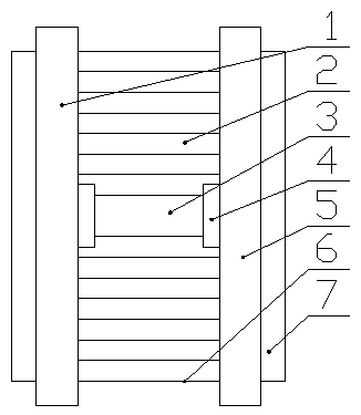
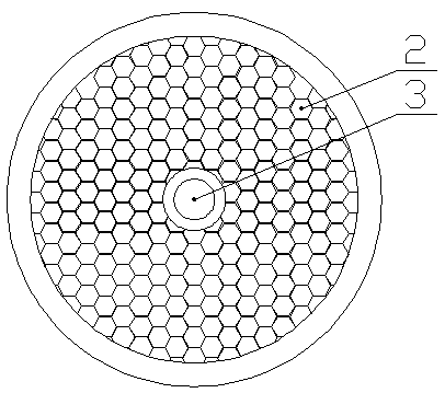
[0015] Such as figure 1 , figure 2 As shown, a dual-mass flywheel includes a first mass flywheel 1 and a second mass flywheel 5. The first mass flywheel 1 is connected to a drive shaft 3 through a bearing 4, and the other end of the drive shaft 3 passes through The bearing 4 is connected with the second mass flywheel 5, and the first mass flywheel 1 and the second mass flywheel 5 are fixed by a honeycomb rubber disc 6, and the honeycomb rubber disc 6 is connected with the first mass flywheel 1, the second mass flywheel 5 The two-mass flywheels are all connected by elastic joints 7, and the honeycomb rubber disc 6 is provided with tight honeycomb holes 2.

[0016] The invention connects the dual-mass flywheel through a honeycomb-shaped rubber disk, and the honeycomb-shaped rubber disk is provided with tight honeycomb holes. The mass flywheel is tightly and completely connected, and the contact area reaches the maximum, so that the dual-mass flywheel reduces vibration, and th...

Embodiment 2

[0018] Such as figure 1 , figure 2 As shown, a dual-mass flywheel includes a first mass flywheel 1 and a second mass flywheel 5. The first mass flywheel 1 is connected to a drive shaft 3 through a bearing 4, and the other end of the drive shaft 3 passes through The bearing 4 is connected with the second mass flywheel 5, and the first mass flywheel 1 and the second mass flywheel 5 are fixed by a honeycomb rubber disc 6, and the honeycomb rubber disc 6 is connected with the first mass flywheel 1, the second mass flywheel 5 The two-mass flywheels are all connected by elastic joints 7, and the honeycomb rubber disc 6 is provided with tight honeycomb holes 2, and the honeycomb rubber disc 6 is flexibly connected to the first mass flywheel 1, so that The honeycomb rubber disc 6 and the second mass flywheel 5 are flexibly connected, the elastic joint 7 can be a rubber joint or a bellows, and the honeycomb hole 2 is closely arranged on the periphery of the drive shaft 3 .

[0019] ...


PUM


Abstract

The invention relates to a dual mass flywheel. The dual mass flywheel comprises a first mass flywheel and a second mass flywheel, wherein the first mass flywheel is connected with a driving shaft through a bearing, the other end of the driving shaft is connected with the second mass flywheel through a bearing, the first mass flywheel is fixed with the second mass flywheel through a honeycomb-shaped rubber disc, the honeycomb-shaped rubber disc is connected with the first mass flywheel and the second mass flywheel through elastic connectors respectively, and the honeycomb-shaped rubber disc isprovided with compact honeycomb holes. The dual mass flywheel has the advantages that the structure is simple, the damping effect is good, the dual mass flywheel is resistant to wear, the service lifeis long, the practicability is high, and the use is convenient.

Description

technical field [0001] The invention belongs to the technical field of auto parts, and in particular relates to a dual-mass flywheel. Background technique [0002] Dual-mass flywheel is usually used as a shock absorber in the process of power transmission of automobiles to reduce the torsional vibration of the output shaft of the engine, so that the automobile has better NVH performance. The dual-mass flywheel is generally arranged between the engine and the gearbox, and the output shaft of the engine is fixedly connected to one of the flywheels to drive the flywheel to rotate; the other mass flywheel is adapted to be fixed with the input shaft of the gearbox to transmit power to In the prior art, the two quality flywheels are connected through various types of springs, and the relative rotation between the two flywheels is used to eliminate torsional vibrations, but no matter what type of spring, the same as the double The contact area of ​​the mass flywheel is limited, th...

Claims


Application Information

Patent Timeline
Patent Type & Authority Applications(China)
IPC IPC(8): F16F15/30F16F15/124
CPCF16F15/124F16F15/30
Inventor 李战营杨晓雷李俊伟
Owner 禹州市竹园机械制造有限公司
Why Eureka
Eureka Blog
Learn More