
Annular nozzle propeller

An annular nozzle and thruster technology, applied in the aerospace field, can solve problems such as low efficiency, small fuel combustion space, and reduced combustion efficiency, and achieve the effects of improving efficiency, increasing fuel combustion space, and reducing projected area.

Active Publication Date: 2021-03-26
梁智斌
View PDF4 Cites 0 Cited by
  • Summary
  • Abstract
  • Description
  • Claims
  • Application Information

AI Technical Summary

Problems solved by technology

[0003] Existing common aerospace thrusters are mainly composed of fairings, casings, fuel tanks, solid fuels, nozzles, and nozzle post-processors. Generally, solid fuels are fully loaded in the fuel tanks coaxially with the entire propeller, while solid fuels The gas channel in the gas channel is only a columnar channel in the projection direction of the nozzle. The defect of this general design is that under the requirement of a certain fuel volume, the gas channel is too thin, the fuel combustion space is too small, and the efficiency is not high; at the same time, because the solid fuel is burned from the center Expand to the edge, so in the combustion process between traditional columnar fuels, due to the increase in distance from the center of the combustion channel, the combustion efficiency drops significantly

Method used


Image

  • Annular nozzle propeller
  • Annular nozzle propeller
  • Annular nozzle propeller

Examples


Embodiment 1

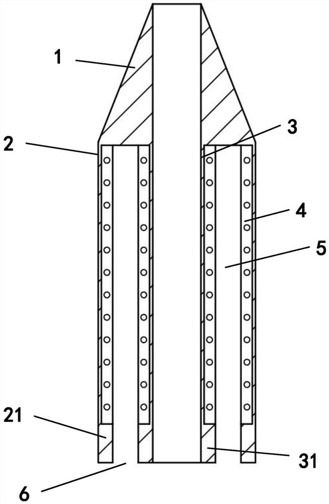
[0019] Such as figure 1 As shown, the annular nozzle propeller includes a fairing 1, a propeller casing 2, a solid fuel chamber and a solid fuel 4 arranged in the solid fuel chamber, and is characterized in that: it also includes a coaxial arrangement with the propeller casing 2. The cylindrical propeller inner shell 3, the upper edge of the propeller inner shell 3 is sealingly connected with the upper edge of the propeller outer shell 2, and the solid fuel chamber is between the propeller outer shell 2 and the propeller inner shell 3 A ring-shaped fuel chamber is formed between them, the gap between the lower edge of the propeller inner shell 3 and the lower edge of the propeller outer shell 2 forms an annular nozzle 6, and the lower edge of the propeller inner shell 3 is thickened and extended radially outward to form a The inner wall 31 of the nozzle, the lower edge of the propeller casing is thickened radially inward to form the outer wall 21 of the nozzle, the interior of...


PUM


Abstract

The invention discloses an annular nozzle propeller. The annular nozzle propeller comprises fairing, a propeller outer casing, a solid fuel chamber and solid fuel arranged in the solid fuel chamber, and is characterized by further comprising a cylindrical propeller inner casing coaxial with the propeller outer casing, the upper edge of the propeller inner casing is in sealed connection with the upper edge of the propeller outer casing, an annular cylindrical fuel chamber body of the solid fuel chamber is formed between the propeller outer casing and the propeller inner casing, and an annular nozzle is formed in a gap between the lower edge of the propeller inner casing and the lower edge of the propeller outer casing. The annular nozzle propeller has the advantages that the projection areais greatly reduced compared with that of a traditional gas channel, and the speed of discharging a working medium is higher.

Description

technical field [0001] The invention belongs to the field of aerospace technology, and in particular relates to an annular nozzle propeller. Background technique [0002] At present, many civil and commercial aerospace companies have emerged at home and abroad, and each aerospace company uses different technologies. The commercial aerospace giant space X increases the power by increasing the number of engines; Blue Origin increases the volume of the rocket and increases the fuel to increase the power; The improvement of rocket engine design in the world is basically based on the fuel formula, while the design of the propeller nozzle and the shape of the fuel tank have not changed much in terms of the overall design. [0003] Existing common aerospace thrusters are mainly composed of fairings, casings, fuel tanks, solid fuels, nozzles, and nozzle post-processors. Generally, solid fuels are fully loaded in the fuel tanks coaxially with the entire propeller, while solid fuels ...

Claims


Application Information

Patent Timeline
Patent Type & Authority Patents(China)
IPC IPC(8): F23R5/00
CPCF23R5/00
Inventor 梁智斌
Owner 梁智斌
Learn More