Combustor for industrial furnace

A technology for burners and industrial furnaces, applied in burners, gas fuel burners, combustion methods, etc., can solve the problems of insufficient mixing of air and fuel, failure to use reasonably, insufficient fuel combustion, etc., and achieve convenient application. , avoid radiation loss, the effect of improving the effective utilization rate

Inactive Publication Date: 2015-06-24
浙江绍兴世纪能源有限公司
View PDF5 Cites 0 Cited by
  • Summary
  • Abstract
  • Description
  • Claims
  • Application Information

AI Technical Summary

Problems solved by technology

[0003] However, the heating effect of this burner is not ideal. On the one hand, the mixing of air and fuel is not sufficient, resulting in insufficient fuel combustion during the combustion process, low fuel utilization, and poor thermal effect; on the other hand, Since the combustion process takes place in the combustion chamber 2a, the combustion chamber 2a cannot completely transfer the heat generated by the fuel to the materials to be heated in the industrial furnace, and a large part of the heat is radiated to the ambient air, which cannot be used reasonably

Method used


Image

  • Combustor for industrial furnace
  • Combustor for industrial furnace
  • Combustor for industrial furnace

Examples


Embodiment 1

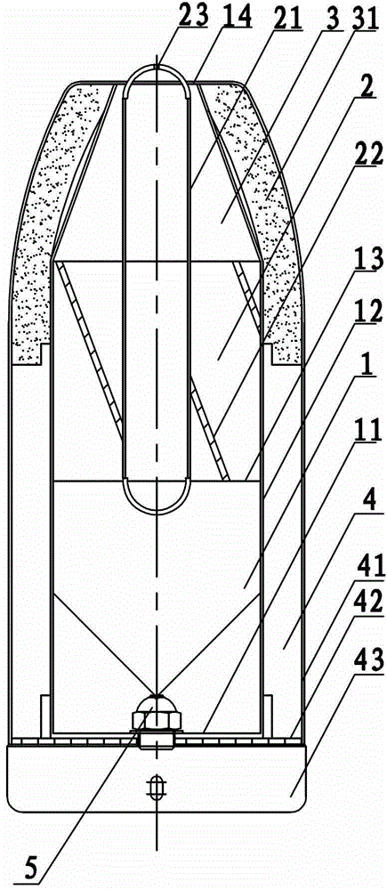
[0022] The present embodiment industrial furnace burner, combines image 3 , including the combustion chamber 1 surrounded by the bottom cover 11, the side wall 12 and the opening 13, the bottom cover 11 is connected to the fuel through the fuel pipe 6; the top of the side wall 12 forms a fire outlet 14, and the fire outlet 14 is located above the opening 13, and the side wall 12. The upper part is provided with a thermal insulation cover 31, and the thermal insulation cover 31 forms the thermal insulation chamber 3 between the opening 13 and the fire outlet 14; The lower part of 12 forms the air chamber 4, and the air chamber 4 is connected with the combustion chamber 1 through the side wall 12 provided with air holes. 44 connect the wind source provided by blower 45; be provided with heating chamber 2 between combustion chamber 1 and heat preservation chamber 3, heat chamber 2 is the space between heat preservation chamber 3 and combustion chamber 1, and guide pipe 21 is arr...

Embodiment 2

[0026] The working principle and setting of this embodiment are the same as those in Embodiment 1, the difference being that the angle of inclination θ of the guide blades 22 is 35°, 6 pieces are evenly arranged, the increase of the angle of inclination increases the quantity of the guide blades 22 simultaneously, The contact area between the flame and the guide vane 22 can be increased, thereby increasing the heating surface of the heat conducting air plate 22, which can better heat the passing fuel and further improve the combustion efficiency.

Embodiment 3

[0028] The working principle and setting of this embodiment are the same as those in Embodiment 1, the difference is that the inclination angle θ of the guide vanes 22 is 20°, and there are 10 uniformly arranged, and the increase of the number of guide vanes 22 can increase the flame and the guide vanes. 22, so that the actual heating surface of the heat-conducting air plate 22 also increases, which can better heat the passing fuel and further improve the combustion efficiency.


PUM


Abstract

The invention relates to a combustor for an industrial furnace, and belongs to the technical field of combustors. The combustor for the industrial furnace comprises a combustion chamber defined by a bottom cover, a lateral wall and an opening, wherein the bottom cover is connected to fuel through a fuel pipe, a flame outlet is formed in the top end of the lateral wall and is located above the opening, a heat preservation cover covers the upper portion of the lateral wall, the heat preservation cover forms a heat preservation chamber between the opening and the flame outlet, an air cover is arranged outside the heat preservation cover, the air cover, the heat preservation cover and the lateral wall form an air chamber at the lower portion of the lateral wall, and the air chamber is communicated with the combustion chamber through the lateral wall with an air hole, and is connected to an air source through a poroid air plate and an air inlet pipe at the bottom of the air chamber. The combustor for the industrial furnace has the advantages of being high in combustion efficiency, convenient and fast to apply and the like, and can be applied to existing industrial furnaces.

Description

technical field [0001] The invention relates to a burner for industrial furnaces, belonging to the technical field of burners. Background technique [0002] A burner commonly used in industrial furnaces mainly includes a burner body 1a, and a combustion chamber 2a is formed inside the body. One end of the combustion chamber 2a is a flame opening 3a, and the other end is connected to a gas source and / or a fuel source 5a. When in use, open the valve 4a , fuel and air are delivered to the combustion chamber 2a, the fuel and air are mixed in the combustion chamber 2a and burned together, the burning flame radiates to the material to be heated in the industrial furnace through the flame opening 3a, and the material is heated or melted. [0003] However, the heating effect of this burner is not ideal. On the one hand, the mixing of air and fuel is insufficient, resulting in insufficient fuel combustion during the combustion process, low fuel utilization, and poor thermal effect; o...

Claims


Application Information

Patent Timeline
Patent Type & Authority Patents(China)
IPC IPC(8): F23D11/00F23D14/00
Inventor 李华良
Owner 浙江绍兴世纪能源有限公司
Why Eureka
Try Eureka