Heat exchange module and heat exchanger

A technology of heat exchange modules and heat exchangers, applied in indirect heat exchangers, heat transfer modification, heat exchange equipment, etc. problems such as full play and low heat transfer efficiency

Inactive Publication Date: 2019-01-18
MIDEA GRP CO LTD
View PDF6 Cites 0 Cited by
  • Summary
  • Abstract
  • Description
  • Claims
  • Application Information

AI Technical Summary

Problems solved by technology

The fluid flows through each microtube, and there is a wake at the end of the microtube, which leads to a relatively large negative pressure in the tail of the microtube, low heat transfer efficiency in the wake area, and a lar

Method used


Image

  • Heat exchange module and heat exchanger
  • Heat exchange module and heat exchanger
  • Heat exchange module and heat exchanger

Examples


Embodiment Construction

[0023] Specific embodiments of the present invention will be described in detail below in conjunction with the accompanying drawings. It should be understood that the specific embodiments described here are only used to illustrate and explain the present invention, and are not intended to limit the present invention.

[0024] In the present invention, unless stated otherwise, the used orientation words such as "up, down, left, right" generally refer to the directions shown in the drawings or to vertical, perpendicular or gravity The terms used to describe the mutual positional relationship of each component in terms of direction.

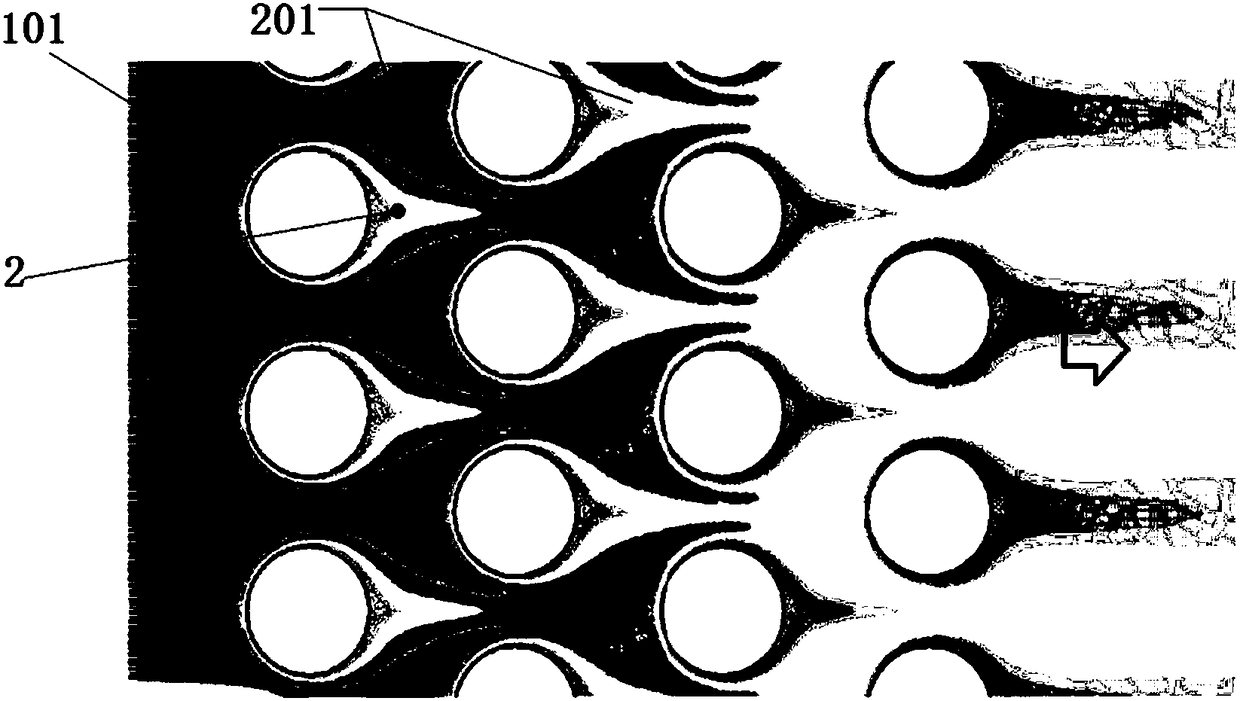
[0025] In addition, the "front row and rear row" in the present invention mean "front and rear" with respect to the flow direction of the external heat exchange fluid. Here, "front row and rear row" should be understood as relative concepts, that is, among the two adjacent rows of microtube groups along the flow direction of the external heat excha...


PUM


Abstract

The invention discloses a heat exchange module and a heat exchanger. The heat exchange module includes multiple rows of micro-pipe sets (1) arranged at intervals in sequence in a flowing direction (F)of an external heat exchange fluid, wherein each row of micro-pipe set (1) comprises a plurality of micro-pipes (101) arranged at intervals in a direction (D) perpendicular to the flowing direction(F); in the flowing direction (F), the row spacing Pr of the adjacent two rows of the micro-pipe sets (1) is sequentially decreased, and any two adjacent rows of micro-pipe sets (1) are arranged in astaggered manner in the vertical direction (D); and by increasing the row spacing of the front rows, the heat exchange effect of the front row of micro-pipe sets is preferentially enhanced to enhancethe exchange coefficient of the heat exchanger in the case of the same pressure drop.

Description

technical field [0001] The invention relates to the field of heat exchangers, in particular to a heat exchange module using microtubes and a heat exchanger with the heat exchange module. Background technique [0002] At present, the key research direction of heat exchangers is microtube heat exchangers, that is, microtubes with small diameters are used as heat exchange tubes. The heat exchange efficiency inside the tube is greatly enhanced by adopting a small-scale tube diameter. On the outside of the tube, due to the small tube diameter, this type of heat exchanger has a much larger specific surface area than conventional heat exchangers. Therefore, this type of heat exchanger Even if the heat exchanger is not provided with fins, it can also achieve the effect of enhancing overall heat dissipation. [0003] The purpose of micro-tube heat exchangers is to enhance heat dissipation. Therefore, the distribution of micro-tubes in the heat exchanger is often relatively dense. T...

Claims


Application Information

Patent Timeline
IPC IPC(8): F28D21/00F28F13/00
CPCF28D21/00F28F13/00F28F2260/02
Inventor 岳宝欧汝浩
Owner MIDEA GRP CO LTD
Why Eureka
Try Eureka