
Pneumatic circulating type pipe drift diameter detecting device and pipe drift diameter detecting method

A detection device and cyclic technology, applied in the direction of mechanical diameter measurement, etc., can solve the problems of high labor intensity, low labor efficiency, and inability to cycle operations, and achieve the effect of high labor intensity and low labor efficiency.

Active Publication Date: 2019-01-18
BAOJI PETROLEUM MASCH CO LTD +2
View PDF6 Cites 0 Cited by
  • Summary
  • Abstract
  • Description
  • Claims
  • Application Information

AI Technical Summary

Problems solved by technology

The manual diameter method is to put the standard diameter gauge from the box end of the pipe string. During the process of hoisting the pipe string to the drill floor with the wind winch, the diameter gauge falls from the male end under the action of gravity. It proves that the diameter of the pipe string meets the standard; this method has the following disadvantages: 1) The efficiency of manual operation is low, the large-scale diameter gauge is heavy, the work is labor-intensive, and there is a certain safety risk in the process of falling the diameter gauge; 2) After the unqualified pipe string is detected, the pipe string needs to be pulled back to the ground, which affects the overall operation efficiency. At the same time, the drift gauge stuck in the pipe string needs to be removed with the help of other tools
The pneumatic method is to blow the drift gauge from one end of the pipe string to the other end with compressed air on the surface of the well site. This method blows air at one end and does not receive it at the other end, and cannot circulate the operation. At least two people are required to participate in the operation, so the pneumatic method is adopted Detecting the diameter of oil pipes and casings also has the problems of low operating efficiency and high risk

Method used


Image

  • Pneumatic circulating type pipe drift diameter detecting device and pipe drift diameter detecting method
  • Pneumatic circulating type pipe drift diameter detecting device and pipe drift diameter detecting method
  • Pneumatic circulating type pipe drift diameter detecting device and pipe drift diameter detecting method

Examples


Embodiment Construction

[0028] The present invention will be described in detail below in conjunction with the accompanying drawings and specific embodiments.

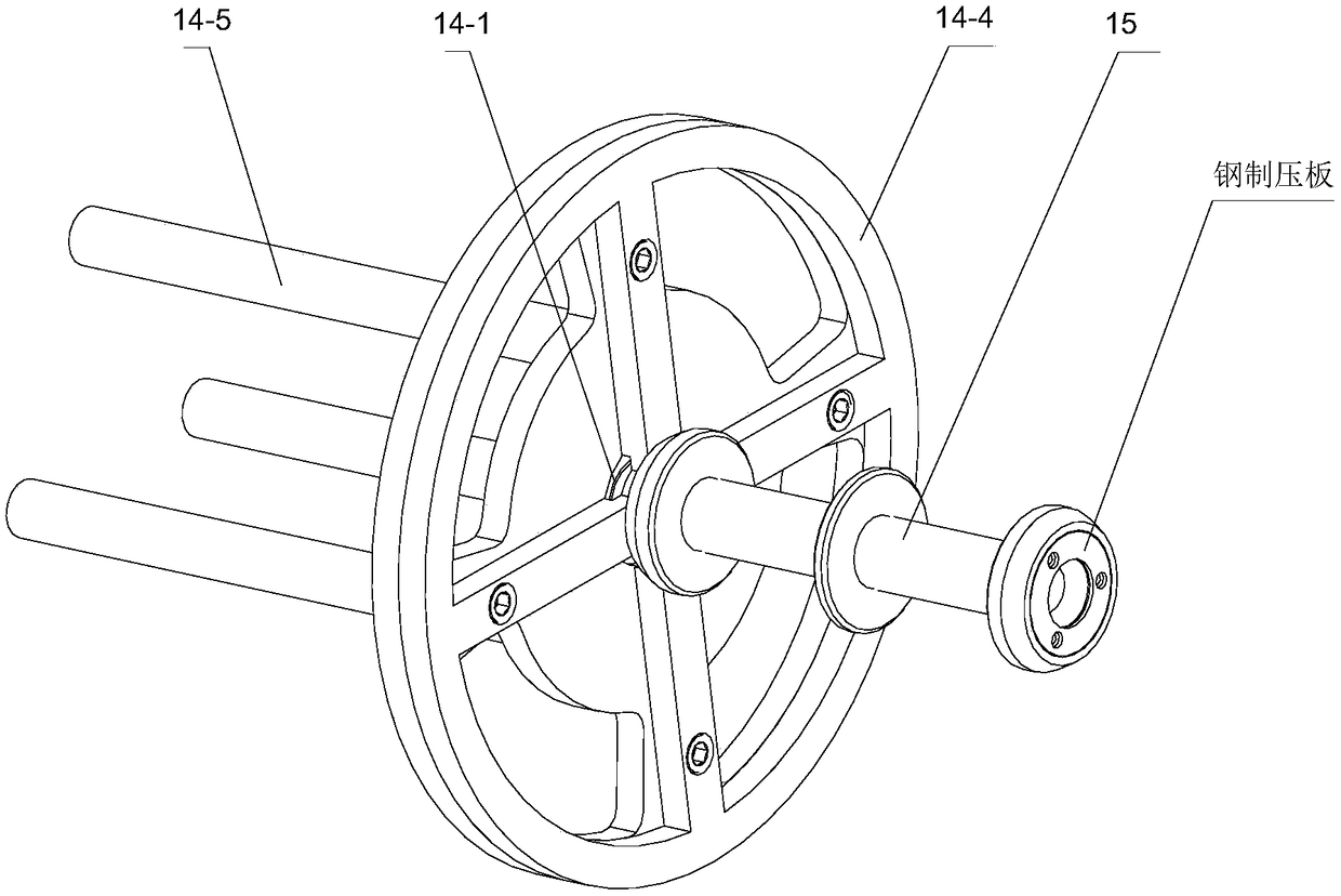
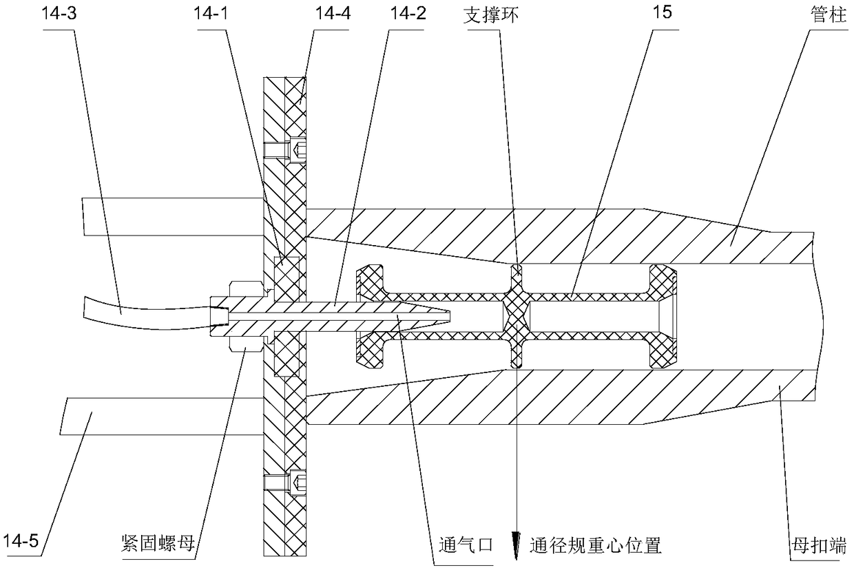
[0029] The invention provides a pneumatic circulation pipeline diameter detection device, such as figure 1 As shown, the base 1 is included, and the base 1 is arranged on the ground of the drilling site, which is a closed structure; a detection unit is arranged at both ends of the base 1, and each detection unit includes a path detection mechanism assembly 14, and each path detection mechanism The assembly 14 is connected with a diameter gauge 15, and at least two pipe column positioning frames 2 are arranged on the base 1 between the two detection units. There is a kick-out mechanism, which can realize the automatic kicking out of the pipe string. The pipe string is placed on the pipe string positioning frame 2, and the air control valve group 4 and the controller 5 are also arranged on the base 1. The detection unit is connected with the ai...


PUM


Abstract

The invention discloses a pneumatic circulating type pipe drift diameter detecting device, which comprises a base. A detecting unit is respectively fixedly connected at the two ends of the base; eachdetecting unit comprises a drift diameter detecting mechanism assembly; each of the drift diameter detecting mechanism assemblies is connected with a drift diameter gauge; at least two pipe string positioning frames are arranged on the base between the two detecting units; the base is also provided with a pneumatic control valve group and a controller, which are interconnected with each other; thedetecting unit is respectively connected with the pneumatic control valve group and the controller; and the pneumatic control valve group is also connected with an air source port. The device in theinvention realizes automatic circulating drift diameter operation of the two ends of the pipe string; an unfreezing method when the drift diameter is unqualified is also increased; the controller canbe also used for operation; the automatic degree is high; the labor intensity is greatly reduced; the device is simple and practical; and the equipment investment cost is low.

Description

technical field [0001] The invention belongs to the technical field of petroleum drilling and production equipment, and relates to a pneumatic circulation type pipeline diameter detection device, and also relates to a pipeline diameter detection method. Background technique [0002] The diameter of tubing and casing, that is, whether the inner diameter and straightness are qualified, will affect the normal drilling work for a long time. If the diameter of the tubing and casing is unqualified, the detection tools and rubber plugs will be stuck in the tubing and casing, which will not only affect the drilling efficiency, but also may cause the entire well to be scrapped. Therefore, it is imminent to solve the problem of the diameter of the tubing and casing on the drilling site, and a device and operation method are urgently needed to screen out the tubing and casing that do not meet the standards before going into the well. [0003] At present, manual and pneumatic methods a...

Claims


Application Information

Patent Timeline
IPC IPC(8): G01B5/12
CPCG01B5/12
Inventor 韩亚洲张志伟王耀华栾苏刘锐玖
Owner BAOJI PETROLEUM MASCH CO LTD
Learn More