
Multi-core fiber microbend sensor

A microbend sensor, multi-core optical fiber technology, applied in instruments, measurement of force by measuring the change of optical properties of materials when they are stressed, measuring devices and other directions, can solve problems such as directions that cannot sense pressure

Inactive Publication Date: 2019-01-18
NANJING UNIV OF POSTS & TELECOMM
View PDF11 Cites 2 Cited by
  • Summary
  • Abstract
  • Description
  • Claims
  • Application Information

AI Technical Summary

Problems solved by technology

[0004] Although the optical fiber micro-bend pressure sensor has many unique advantages such as small size, light weight, strong anti-electromagnetic interference ability, and ability to adapt to harsh working environments (Liu Changhua, Xu Yajun. Distributed optical fiber stress based on optical time domain reflectometry Sensors. [J]. Instrument Technology and Sensors, 2005, 3(6): 3-5.), but the existing optical fiber microbending pressure sensors still have certain defects, for example, a single optical fiber microbending pressure sensor can only detect The magnitude of the pressure in a fixed direction, but the direction of the pressure cannot be sensed

Method used


Image

  • Multi-core fiber microbend sensor
  • Multi-core fiber microbend sensor

Examples


Embodiment Construction

[0016] Objects, advantages and features of the present invention will be illustrated and explained by the following non-limiting description of preferred embodiments. These embodiments are only typical examples of applying the technical solutions of the present invention, and all technical solutions formed by adopting equivalent replacements or equivalent transformations fall within the protection scope of the present invention.

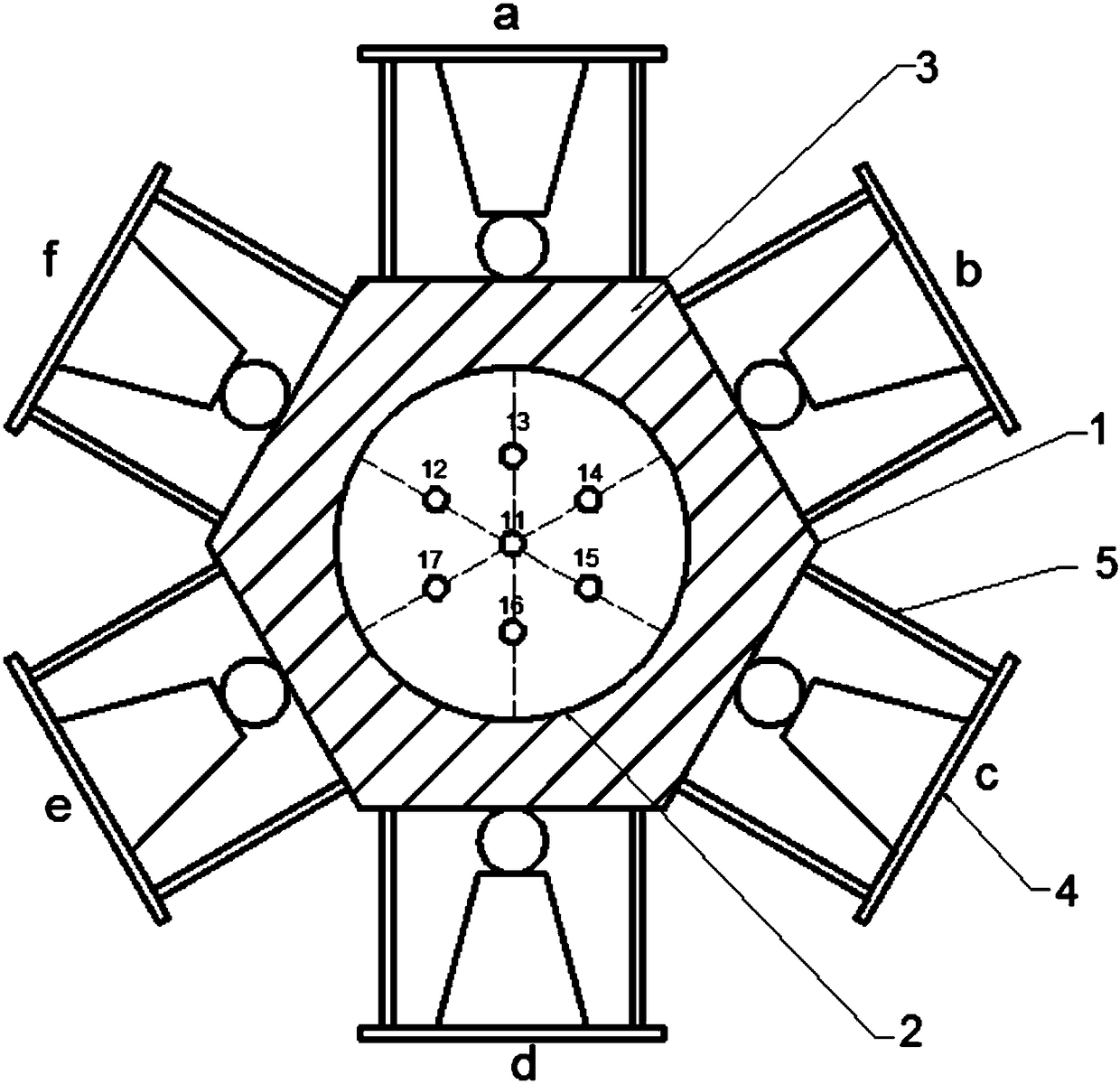
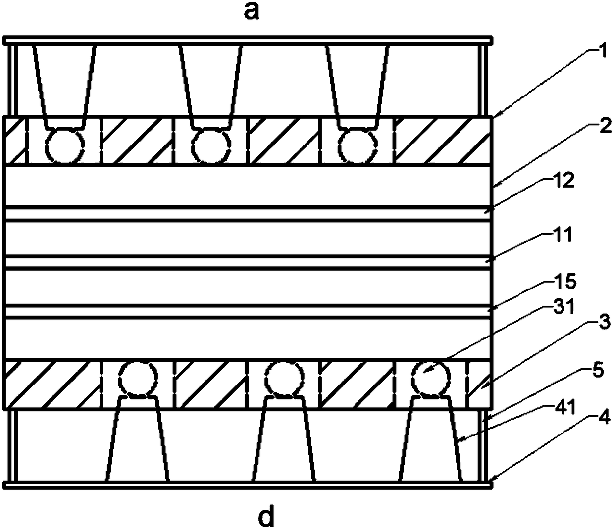
[0017] The invention discloses a multi-core optical fiber microbend sensor, such as figure 1 As shown, the sensor includes a fixed sleeve 1, a multi-core optical fiber 2, and a deformer 4. The fixed sleeve is made of a rigid material, and the multi-core optical fiber is arranged in the middle of the fixed sleeve. The fixed sleeve and the The gaps of the multi-core optical fiber are filled with flexible material 3, and the flexible material filled in the sleeve is a foam material, and the foam material is sponge or foam rubber.

[0018] The fixing sl...


PUM


Abstract

The invention discloses a multi-core fiber microbend sensor. The sensor comprises a fixed pipe sleeve, a multi-core fiber, and a deformer, wherein the fixed pipe sleeve is made of a rigid material, the multi-core fiber is arranged in the middle of the fixed pipe sleeve, a clearance between the fixed pipe sleeve and the multi-core fiber is filled with a flexible material, the fixed pipe sleeve andthe deformer are connected through an elastomer structure, the deformer is made of the rigid material, and the deformer is provided with periodic deformation teeth. External pressure is transferred toa fiber microbend deformer through deformation of the deformer, so that the periodic deformation teeth in the fiber microbend deformer act on the multi-core fiber in the fixed pipe sleeve, then the multi-core fiber bends slightly, different fiber cores in the multi-core fiber have different curvature radiuses of microbending due to different spatial positions, therefore, different fiber cores aredifferent in microbending loss, external pressure and direction change can be learnt according to losses of optical signals in different fiber cores, and external pressure and direction can be sensedat the same time.

Description

technical field [0001] The invention relates to a multi-core optical fiber micro-bending sensor, relates to the technical field of optical fiber sensing, in particular to a pressure micro-bending sensor based on a multi-core optical fiber, capable of measuring the magnitude and direction of external pressure. Background technique [0002] When light is transmitted in the optical fiber, the phase and amplitude of the light wave will change due to external temperature, pressure, vibration and other factors. The optical fiber sensor is a sensor that uses this principle to detect changes in physical quantities. Since the optical path of the optical fiber is closed, the optical fiber sensor is more suitable for measurement in harsh environments such as high temperature and high pressure, flammable, explosive, and corrosive conditions. Therefore, fiber optic sensors have been widely used in aerospace, oil exploration, automatic control and other fields. [0003] As an important o...

Claims


Application Information

Patent Timeline
IPC IPC(8): G01L1/24
CPCG01L1/245
Inventor 陆云清吴祥许炯许吉王瑾
Owner NANJING UNIV OF POSTS & TELECOMM
Learn More