
Device and method for measuring axial thrust of centrifugal compressor

A centrifugal compressor, axial thrust technology, applied in measuring devices, force/torque/power measuring instruments, instruments, etc., can solve problems such as complex internal structure, abnormal operation of the whole unit, complex structure of the unit, etc.

Inactive Publication Date: 2019-01-18
SHENYANG POLYTECHNIC UNIV
View PDF5 Cites 1 Cited by
  • Summary
  • Abstract
  • Description
  • Claims
  • Application Information

AI Technical Summary

Problems solved by technology

For centrifugal compressors, due to the complex internal structure and numerous components, any problem with any component or link during the entire operation stage will cause the entire device to fail
Among them, due to the axial thrust, the thrust bearing wears out or the temperature of the thrust pad is too high, causing the entire unit to fail to operate normally. This problem is one of the main reasons for the failure of centrifugal compressors, and it is also a problem that plagues the compressor equipment manufacturing industry.
[0003] Usually the working medium of the centrifugal compressor is not single, and the structure of the whole unit is complex, so if you want to accurately simulate the axial thrust of the centrifugal compressor, there is a certain gap between the result and the actual force situation

Method used


Image

  • Device and method for measuring axial thrust of centrifugal compressor
  • Device and method for measuring axial thrust of centrifugal compressor
  • Device and method for measuring axial thrust of centrifugal compressor

Examples


Embodiment Construction

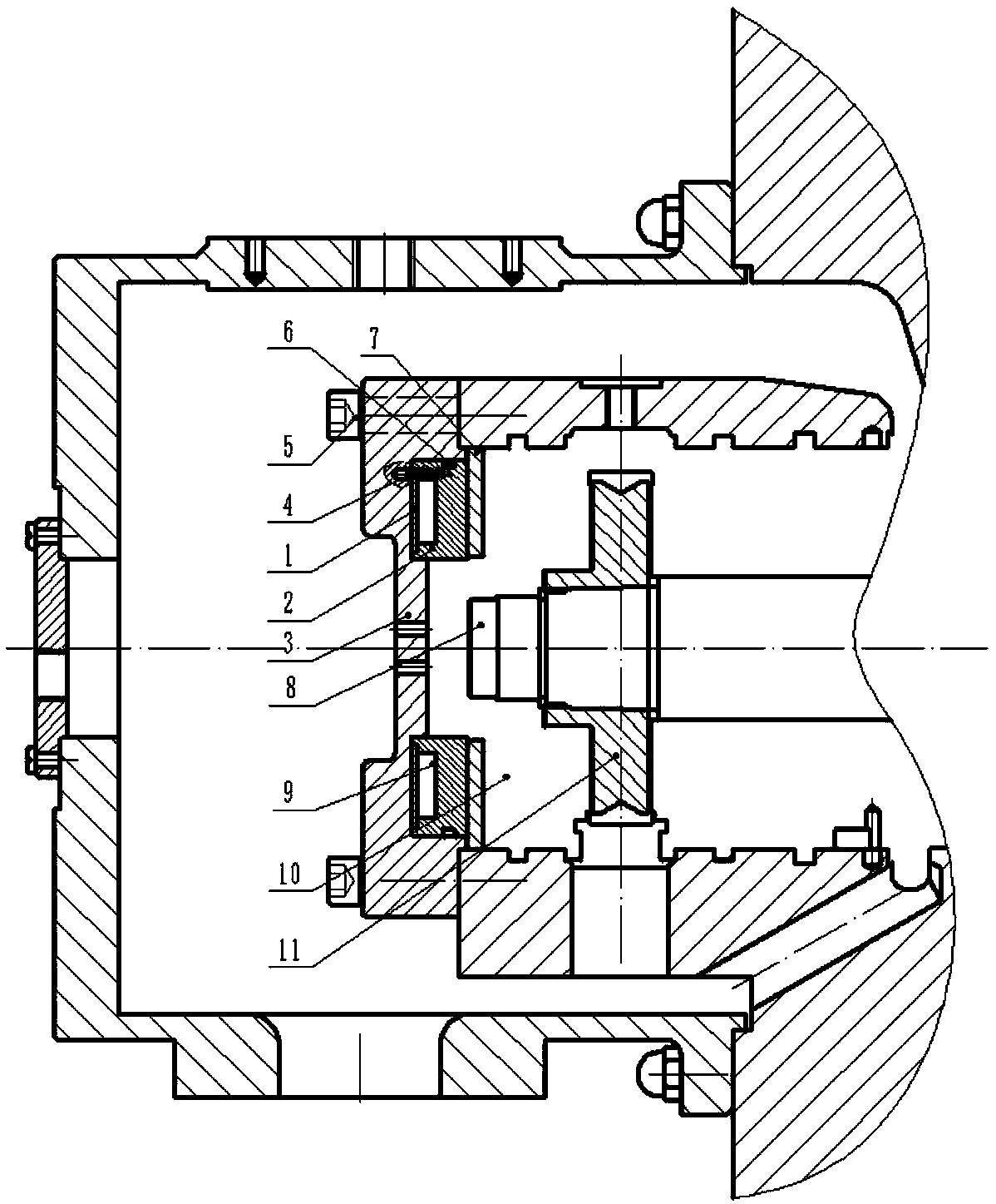
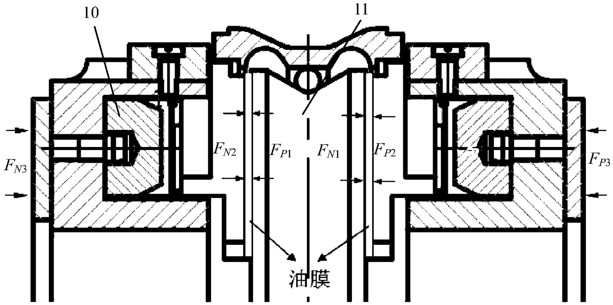
[0027] A centrifugal compressor axial thrust measurement device, comprising a compressor casing and a centrifugal compressor main shaft (8) arranged in the compressor casing, the device is installed on the tail end side of the centrifugal compressor main shaft (8), and the device includes a measuring The force-measuring end face (1) of the force-measuring device, the constraint end face (2) of the force-measuring device, the blind flange (3), the gasket (7), the thrust bearing (10) and the thrust plate (11);

[0028] The gasket (7) is installed on the side close to the main shaft (8) of the centrifugal compressor in the compressor casing, (ie figure 1 The left side of the centrifugal compressor main shaft (8) in the center) the constraint end surface (2) of the force measuring device is installed on the left side of the gasket (7), (that is, the gasket (7) is at the constraint end surface (2) and the centrifugal compressor Between the thrust bearings (10!) the force-measuring ...


PUM


Abstract

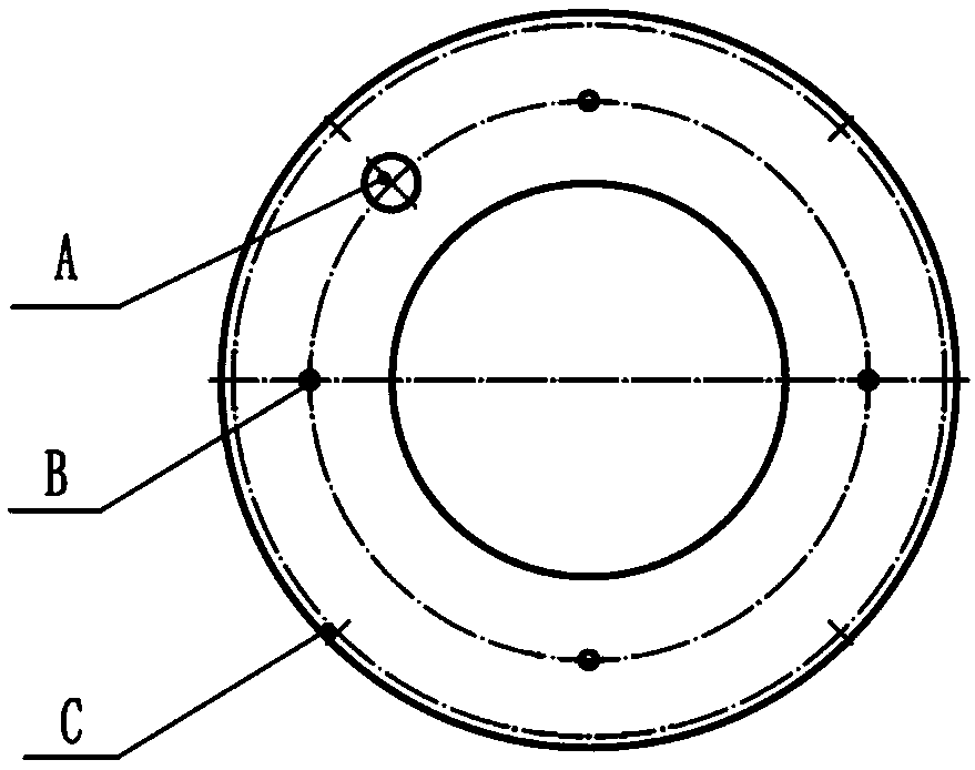
The invention provides a device and a method for measuring an axial thrust of a centrifugal compressor. The device is installed at the tail end side of the main shaft in the casing of the centrifugalcompressor. The device comprises a thrust measuring end face of the thrust measuring device, a restraining end face of the thrust measuring device, a blind flange, a gasket, a thrust bearing and a thrust disk. 1. The measuring method of the invention is realized by the thrust measuring device, the blind flange, the gasket, the thrust bearing, the thrust disk, a signal conditioning system and a data acquisition system. 2. The number of thrust measuring points on the cover plate of the thrust measuring device of the invention can be 3-6, and each thrust measuring point should ensure accurate flatness. 3. The outer ring of the restraining end face of the thrust measuring device of the invention is designed with an o-ring groove, and the thrust measuring device and the blind flange can realizeflexible assembly. The thrust measuring points on the cover plate of the thrust measuring device are in point contact with the inner end face of the blind flange, and the restraining end face of thethrust measuring device is in contact with the gasket.

Description

technical field [0001] The invention provides a real-time measurement method for the axial thrust of a fluid mechanical centrifugal compressor, which belongs to the technical field related to the measurement of the axial thrust of a fluid mechanical centrifugal compressor. Background technique [0002] In the fields of petroleum and chemical industry, the safe and reliable operation of centrifugal compressors directly affects the development of the national economy. For centrifugal compressors, due to the complex internal structure and numerous components, any problem in any part or link during the entire operation stage will cause the failure of the entire device. Among them, due to the axial thrust, the thrust bearing is worn or the thrust pad temperature is too high, so that the whole unit cannot operate normally. This problem is one of the main reasons for the failure of centrifugal compressors, and it is also a problem that plagues the compressor equipment manufacturing...

Claims


Application Information

Patent Timeline
IPC IPC(8): G01L5/12
CPCG01L5/12
Inventor 高翼飞骆嘉朱艾晨饶志坚
Owner SHENYANG POLYTECHNIC UNIV
Learn More