
An assembly device for an automobile dust cover

An assembly device and dust cover technology, applied in metal processing equipment, metal processing, manufacturing tools, etc., can solve the problems of increased workload, reduced work efficiency, and hand disease of workers, so as to achieve flexible assembly and improve product quality. The effect of improving quality and reducing labor intensity

Active Publication Date: 2020-11-20
NINGBO TUOPU IND AUTOMATION CO LTD
View PDF5 Cites 0 Cited by
  • Summary
  • Abstract
  • Description
  • Claims
  • Application Information

AI Technical Summary

Problems solved by technology

The existing assembly method of the dust cover is mainly assembled manually, which has the following disadvantages in the operation process: 1. Manual operation is used on site, the rhythm of manual assembly is slow, the stability and consistency of the product are poor, and the quality cannot be guaranteed; 2. The manually assembled dust cover may not be installed in place, and the follow-up process needs to be inspected, which increases the workload of workers; 3. Manual operation is used on site, which is inconvenient to operate, and the dust cover is easy to bounce off the worker's hand, which will reduce the long-term decline Work efficiency, the labor intensity of the workers is high, resulting in hand diseases of the workers
[0003] In addition, there is currently no dust cover installation mechanism that can meet the requirements of consistent appearance and different sizes.

Method used


Image

  • An assembly device for an automobile dust cover
  • An assembly device for an automobile dust cover
  • An assembly device for an automobile dust cover

Examples


Embodiment 1

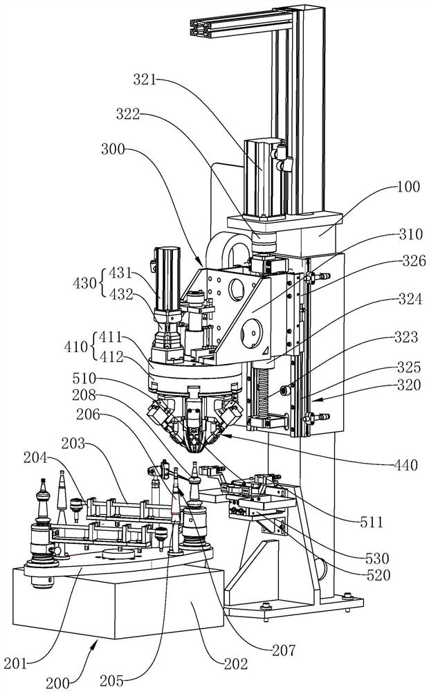
[0040] Embodiment one: if figure 1 As shown, an assembly device for an automobile dust cover includes a frame 100; a rotary table mechanism 200, the rotary table mechanism 200 includes a worktable 201 and a rotary drive motor 202 for driving the rotation of the worktable 201, and the worktable 201 The two ends of the two ends are respectively provided with a limit frame 204 for fixing the product 203 to be installed, and one side of the limit frame 204 is provided with a tapered sleeve limit seat 205, and a tapered sleeve limit seat 205 is placed on the tapered sleeve limit seat 205 for guiding the dust cover 208. The taper sleeve 206, the longitudinal section of the taper sleeve 206 is conical, the taper sleeve 206 is provided with a limiting platform 207, the outer diameter of the limiting platform 207 is about the inner diameter of the upper opening of the dust cover 208, and the limiting platform 207 is used for coarse positioning;

[0041] The vertical press-in mechanism...

Embodiment 2

[0044] Embodiment two: if figure 1 As shown, an assembly device for an automobile dust cover includes a frame 100; a workbench 201, a rotary drive motor 202 is arranged under the workbench 201, and the two ends of the workbench 201 are respectively provided with a limiter for fixing a product 203 to be installed. Position frame 204, one side of limit frame 204 is provided with taper sleeve limit seat 205, is placed on the taper sleeve limit seat 205 and is used for the taper sleeve 206 of dust cover 208 guidance, and the longitudinal section of taper sleeve 206 is conical , the taper sleeve 206 is provided with a limiting platform 207, the outer diameter of the limiting platform 207 is about the inner diameter of the upper opening of the dust cover 208, and the limiting platform 207 is used for rough positioning;

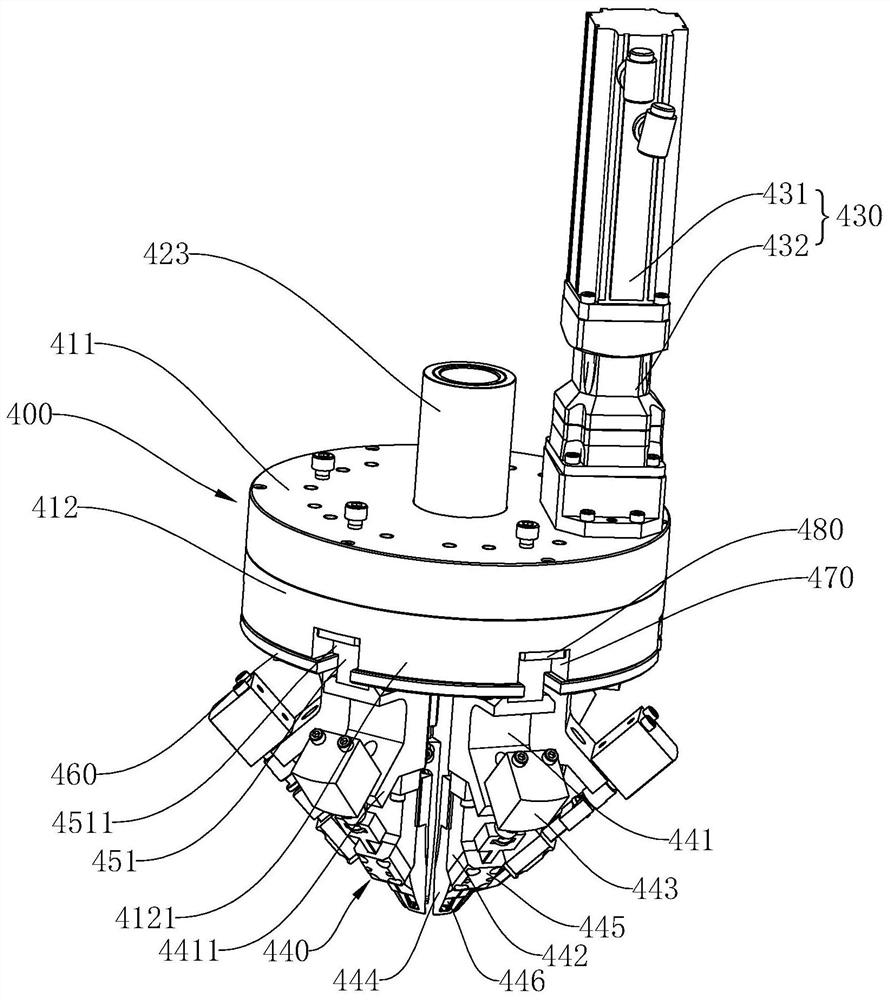
[0045] The vertical press-in mechanism 300, the vertical press-in mechanism 300 includes a mounting frame 310, a vertical conveying mechanism 320 and a jacking mech...

Embodiment 3

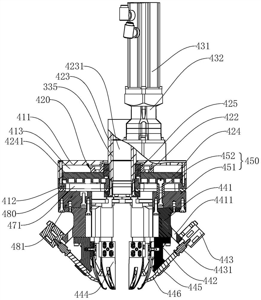
[0053] Embodiment 3: Other structures are the same as Embodiment 2, the difference is that: the middle part of the central shaft 423 is provided with a mounting hole 4231 that penetrates up and down, and the ejector mechanism 330 includes a guide rod sleeve 331, a cover plate 332, and a guide rod 333 , dust cover top barrel 334 and the second drive assembly, the guide rod sleeve 331 is inserted into the installation hole 4231, a guide sleeve 335 is arranged between the central shaft 423 and the guide rod sleeve 331, and the guide rod 333 is vertically penetrated and arranged on the guide rod. In the rod sleeve 331, the cover plate 332 is fixed on the top of the guide rod sleeve 331, the middle part of the guide rod 333 is provided with an outwardly extending limiting plate 336, and the lower end of the guide rod sleeve 331 is provided with an inwardly extending boss 4121, the limit plate 336 is against the boss 4121, a return spring 337 is arranged between the cover plate 332 a...


PUM


Abstract

The invention discloses an assembly device for a car dust cover. When the assembly device is mounted, a driving mechanism is rotated to drive a worktable, so that a to-be-mounted end of a to-be-mounted product is positioned below an ejecting mechanism, a vertical conveying mechanism drives a mounting rack to move downwards along a rack; and a conical sleeve is ejected by the ejecting mechanism, the dust cover is pressed by the ejecting mechanism, the dust cover is opened by an opening mechanism, and at the moment, the vertical conveying mechanism continuously drives the mounting rack to move downwards, the opening mechanism and the ejecting mechanism are driven to move downwards until the dust cover is moved to the to-be-mounted end, and the dust cover is released by the opening mechanismto enable the dust cover to be mounted in place. The assembly device has the advantages that the automatic production is realized, the labor intensity of workers is reduced, the cost is reduced, the dust cover is prevented from being hit on a worker's hand, and the working efficiency is improved; through the adoption of the assembly device, the product is assembled in placed at one time, the capacity tempo is accelerated, the product stability and the consistency are realized, and the product quality is greatly improved; and meanwhile, for a dust cover with the similar characteristics, the size difference is tolerable, multiple product requirements are met, and the flexible assembly is realized.

Description

technical field [0001] The invention relates to an assembly device, in particular to an assembly device for an automobile dust cover. Background technique [0002] At present, in the steering system of automobiles, products such as stabilizer bar connecting rods, control arms and ball joints all need to be installed with dust covers. The dust cover is a kind of rubber part. During the installation process, the dust cover is stretched and then covered on the product to be installed. The dust cover wraps the product to be installed by its own resilience. The existing assembly method of the dust cover is mainly assembled manually, which has the following disadvantages in the operation process: 1. Manual operation is used on site, the rhythm of manual assembly is slow, the stability and consistency of the product are poor, and the quality cannot be guaranteed; 2. The manually assembled dust cover may not be installed in place, and the follow-up process needs to be inspected, wh...

Claims


Application Information

Patent Timeline
Patent Type & Authority Patents(China)
IPC IPC(8): B23P19/00B23P19/02
CPCB23P19/00B23P19/02
Inventor 宋旭华刘武龙唐亚明
Owner NINGBO TUOPU IND AUTOMATION CO LTD
Learn More