Electric conduction probe, use and manufacture method, and method for lowering electric discharge of electric conduction probe

A technology of conductive probes and probes, which is applied to the parts of electrical measuring instruments, measuring electricity, measuring electrical variables, etc., can solve the problems of probe ablation, affecting LED test light parameters and electrical parameters, etc., and achieve reliable use , reduce the smoothness requirements, and the effect of simple structure

Pending Publication Date: 2019-01-18
SHENZHEN SIDEA SEMICON EQUIP
View PDF0 Cites 0 Cited by
  • Summary
  • Abstract
  • Description
  • Claims
  • Application Information

AI Technical Summary

Problems solved by technology

However, as the LED crystal grain becomes smaller and smaller, the discharge between the N-pole probe and the P-pole probe due to the too close distance will cause the probe to accelerate ablation and affect the optical and electrical parameters of the LED test.

Method used


Image

  • Electric conduction probe, use and manufacture method, and method for lowering electric discharge of electric conduction probe

Examples


Embodiment Construction

[0020] In order to facilitate those skilled in the art to understand the technical solution of the present invention, the technical solution of the present invention will be further described in detail below in conjunction with specific embodiments.

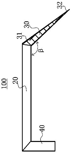
[0021] Such as figure 1 As shown, a conductive probe 100 includes a support part 20 and a bending part 30. The bending part 30 is a part that is connected to the support part 20 and will generate a discharge that affects the use of the conductive probe 100. The support part 20 is used for It is connected to the mounting seat of the conductive probe 100; one end of the support part 20 is electrically connected to the bending part 30, and the electrical signal obtained by the test of the bending part 30 is transmitted to the signal acquisition or processing module through the support part 20, and the support part The included angle between the 20 and the bent portion 30 is β, β∈(90°-180°), which ensures that the support portion 20 ...


PUM


Abstract

The invention discloses an electric conduction probe, a use and manufacture method, and a method for lowering the electric discharge of the electric conduction probe. The electric conduction probe comprises a supporting part and a bending part, wherein one end of the supporting part is electrically connected with the bending part; an included angle [Beta] between the supporting part and the bending part belongs to (90 degrees-180 degrees); the bending part coats high temperature resistant insulating materials; and the bending part comprises an electric contact part. Through the high temperature resistant insulating materials, the electric discharge naked position of the electric conduction probe is coated so as to reduce the electric discharge of the electric conduction probe, and influences on use by the electric discharge of the electric conduction probe is reduced. The electric conduction probe has the advantages of being simple in structure, convenient in production and reliable inuse.

Description

technical field [0001] The invention relates to a conductive probe and a method for using and manufacturing it, and a method for reducing the discharge of the conductive probe. Background technique [0002] For front-mounted and flip-chip LED grains, since the N pole and P pole are on the same side; in order to test the electrical parameters and optical parameters of the LED grain, it is necessary to introduce test electricity to the N pole and P pole of the LED grain at the same time. [0003] At present, the widely used test scheme is: the LED crystal grains are respectively introduced into the test circuit through the test probes. However, as the LED crystal grain becomes smaller and smaller, the discharge between the N-pole probe and the P-pole probe due to the too close distance causes the ablation of the probe to be accelerated and affects the optical parameters and electrical parameters of the LED test. Contents of the invention [0004] In order to improve the N-p...

Claims


Application Information

Patent Timeline
Patent Type & Authority Applications(China)
IPC IPC(8): G01R1/067G01R1/18
CPCG01R1/06761G01R1/18
Inventor 王胜利杨应俊
Owner SHENZHEN SIDEA SEMICON EQUIP
Why Eureka
Try Eureka