A neon lamp transformer capable of dissipating heat

A technology for transformers and neon lights, applied in the field of transformers, can solve the problems of imperfect manufacturing technology, easily damaged transformers, and cumbersome fixing, and achieve the effects of good fixing effect, speeding up heat dissipation, and simple and convenient operation.

Inactive Publication Date: 2019-01-18
SUZHOU HUANYAN ELECTRIC
View PDF0 Cites 0 Cited by
  • Summary
  • Abstract
  • Description
  • Claims
  • Application Information

AI Technical Summary

Problems solved by technology

[0002] The neon lamp is composed of two parts, one part is the neon lamp tube, and the other part is the power supply for driving the lamp tube to emit light, which is what we often call a neon lamp transformer (or a special power supply for neon lamps). The manufacturing technology of neon lamp tubes is very mature. The equipment and manufacturing process are very simple, but the manufacturing technology of the other part of the power supply that drives the lamp tube to emit light, that is, the neon lamp transformer, is not perfect. The gas filled in the neon lamp tube is an inert gas, and it must be broken down by high voltage electricity. It emits colorful light, which cannot be achieved by ordinary electricity. It needs a neon transformer to raise the 220V AC voltage to a high voltage that can break down the inert gas.
[0003] The existing neon lamp transformer fixing method is relatively traditional, and it is cumbersome to fix, and it is not easy to dissipate heat, and it is easy to damage the transformer

Method used


Image

  • A neon lamp transformer capable of dissipating heat
  • A neon lamp transformer capable of dissipating heat

Examples


Embodiment Construction

[0016] The following will clearly and completely describe the technical solutions in the embodiments of the present invention with reference to the accompanying drawings in the embodiments of the present invention. Obviously, the described embodiments are only some, not all, embodiments of the present invention. Based on the embodiments of the present invention, all other embodiments obtained by persons of ordinary skill in the art without making creative efforts belong to the protection scope of the present invention.

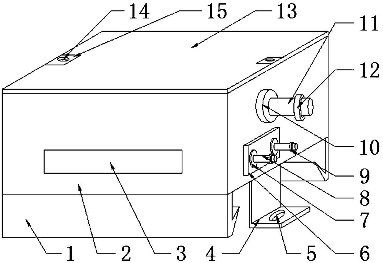
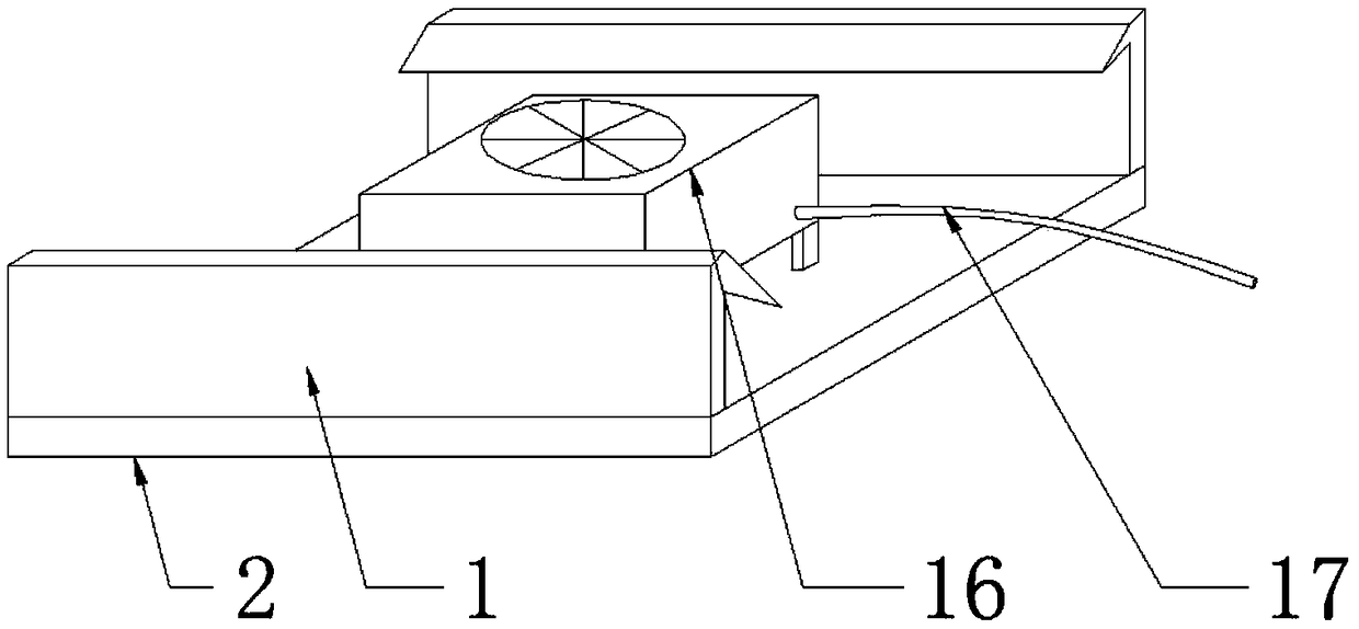
[0017] see Figure 1-2 , the present invention provides a technical solution: a heat-dissipating neon transformer, including a metal case 2 and a top cover 13, the top cover 13 is arranged on the top of the metal case 2, and the surface of the metal case 2 is provided with a penetration plate 6, and the penetration plate 6 is embedded in the metal casing 2, and the surface of the penetration plate 6 is provided with several low-voltage insulating terminals 7, ...


PUM


Abstract

The invention discloses a neon lamp transformer capable of dissipating heat, which includes a metal housing and a top cover, the top cover is arranged on the top of the metal shell, the surface of themetal shell is provided with an insertion board, As that insertion plate is embedded in a metal shell, the surface of the insertion board is provided with a plurality of low-voltage insulating terminals, and the low-voltage insulation terminal is embedded in the insertion board, and evenly distributed in the shape of -, the middle position of the low-voltage insulation terminal is provided with alow-voltage terminal post. According to the heat-dissipating neon lamp transformer, a clamping plate is mounted at the bottom of the metal housing, the metal shell can be conveniently fixed initially, the operation is simple and fast, and the fixing effect is very good, The heat dissipation plate is convenient to dissipate heat inside the metal shell, and protects the electronic components insidethe metal shell. Meanwhile, the blowing fan installed at the bottom of the metal shell can accelerate the heat dissipation speed and further reduce the temperature inside the metal shell.

Description

technical field [0001] The invention relates to the technical field of transformers, in particular to a heat-dissipating neon lamp transformer. Background technique [0002] The neon lamp is composed of two parts, one part is the neon lamp tube, and the other part is the power supply for driving the lamp tube to emit light, which is what we often call the neon lamp transformer (or special power supply for neon lamp). The manufacturing technology of the neon lamp tube is very mature, and the required The equipment and manufacturing process are very simple, but the manufacturing technology of another part of the power supply that drives the lamp tube to emit light, that is, the neon lamp transformer, is not perfect. The gas filled in the neon lamp tube is an inert gas, and it must be broken down by high voltage electricity to It emits colorful light, which cannot be achieved by ordinary commercial electricity. A neon transformer is needed to raise the 220V AC voltage to a high...

Claims


Application Information

Patent Timeline
Patent Type & Authority Applications(China)
IPC IPC(8): H01F27/02H01F27/06H01F27/08H01F27/22H01F38/00
CPCH01F27/02H01F27/06H01F27/085H01F27/22H01F38/00
Inventor 颜欢
Owner SUZHOU HUANYAN ELECTRIC
Why Eureka
Try Eureka