
A tension buffer mechanism

A caching mechanism and tension technology, applied in the direction of sustainable manufacturing/processing, electrochemical generators, electrical components, etc., can solve the problem of inability to maintain a stable tension state of the pole piece, the effect of tension control is not very good, affect product quality and Follow-up procedures and other issues to achieve the effect of improving quality and pass rate, stabilizing tension, and flexible structure

Pending Publication Date: 2019-01-18
GUANGDONG JITI SMART EQUIP CO LTD
View PDF0 Cites 1 Cited by
  • Summary
  • Abstract
  • Description
  • Claims
  • Application Information

AI Technical Summary

Problems solved by technology

[0002] In the existing lithium battery cell production technology, in the manufacturing equipment that completes the pole piece winding process, generally a tension buffer control structure is required between the two driving rollers to eliminate the speed error between the two driving rollers. The tension buffer mechanism is used to dynamically compensate the error value between the driving rollers to ensure a relatively constant tension state during operation. Because the tension is too high, the pole piece will be torn and deformed, and the product will be unqualified if the tension is too small; The winding of the pole piece is in a loose state, which leads to uneven curling, which affects the quality of the product and the subsequent process; while in the prior art, the effect of tension control is not very good, and the tension of the pole piece cannot be kept in a stable state

Method used


Image

  • A tension buffer mechanism
  • A tension buffer mechanism
  • A tension buffer mechanism

Examples


Embodiment Construction

[0027] The present invention will be described in further detail below in conjunction with the accompanying drawings and specific embodiments, and the implementation scope of the present invention is not limited thereto.

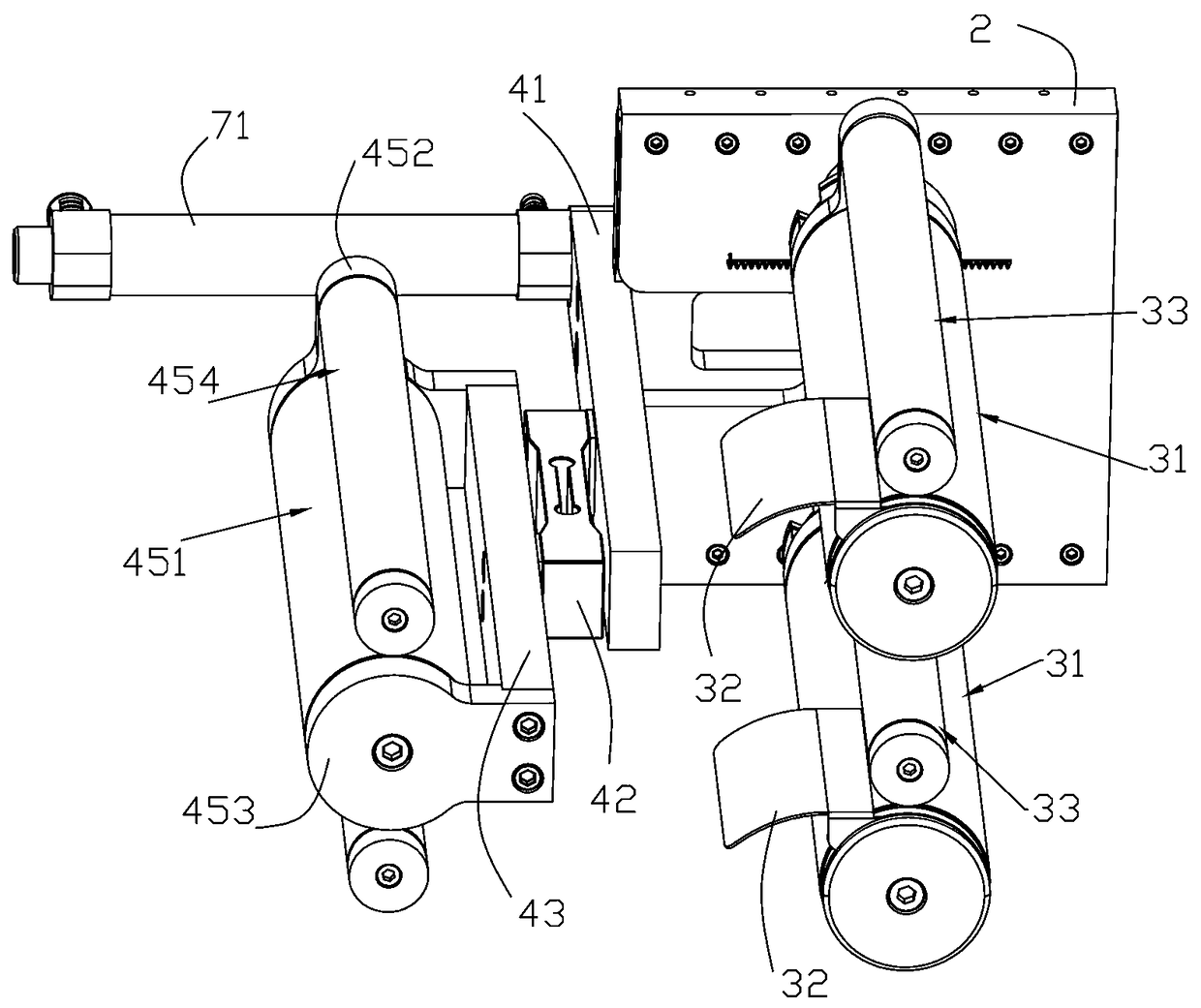
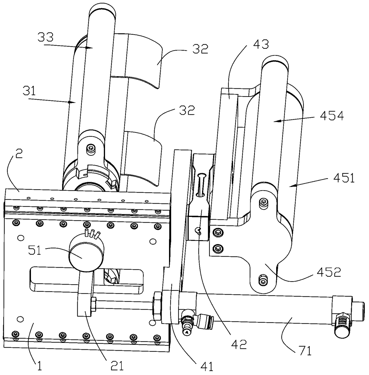
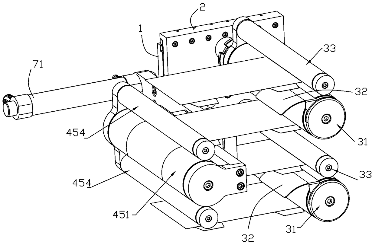
[0028] Such as Figure 1 to Figure 9 As shown, a tension buffer mechanism described in this embodiment includes a driving device, a fixed plate 1, a roller mounting plate 2, a pole piece roller set and a tension detection device, and the roller mounting plate 2 and the fixed plate 1 Sliding connection, the driving device is used to drive the roller mounting plate 2 to slide, the pole piece is set on one side of the roller mounting plate 2 through the roller group, and the tension detection device is arranged on the fixed plate 1 At one end, the pole piece passing roller group is set opposite to the tension detection device, and the tension detection device is used to detect the pole piece tension and feed back to the external control system; it also includes...


PUM


Abstract

A tension buffer mechanism comprises a driving device, a fixing plate, a roller mounting plate, a distance feedback device, a pole plate passing roller group and a tension detecting device; the rollermounting plate is slidably connected with the fixing plate, the driving device is used for driving the roller mounting plate to slide, the electrode sheet passing roller group is arranged on one sideof the roller mounting plate, The tension detecting device is arranged at one end of the fixing plate, and the pole piece passing roller group is arranged opposite to the tension detecting device. The tension detecting device is used for detecting the pole piece tension and feeding back to the external control system, and the distance feedback device is used for detecting the moving distance of the roller mounting plate and feeding back to the external control system. By adopting the structure of the invention, the tension buffer and the detection of the pole piece are realized through the cooperation of the tension detection device and the distance feedback device, so that the tension fluctuation of the pole piece is stable, the running stability of the whole machine running belt is improved, and the tension of the whole machine running belt is stabilized.

Description

technical field [0001] The invention relates to the technical field of lithium battery manufacturing, in particular to a tension buffer mechanism. Background technique [0002] In the existing lithium battery cell production technology, in the manufacturing equipment that completes the pole piece winding process, generally a tension buffer control structure is required between the two driving rollers to eliminate the speed error between the two driving rollers. The tension buffer mechanism is used to dynamically compensate the error value between the driving rollers to ensure a relatively constant tension state during operation. Because the tension is too high, the pole piece will be torn and deformed, and the product will be unqualified if the tension is too small; The winding of the pole piece is in a loose state, which leads to uneven curling, which affects the quality of the product and the subsequent process; and in the prior art, the effect of tension control is not ve...

Claims


Application Information

Patent Timeline
Patent Type & Authority Applications(China)
IPC IPC(8): H01M10/0587B65H26/04B65H23/26
CPCH01M10/0587B65H23/26B65H26/04Y02E60/10Y02P70/50
Inventor 张祥领
Owner GUANGDONG JITI SMART EQUIP CO LTD
Learn More