
A forward and reverse switching device and a single-phase series motor

A switching device, forward and reverse technology, used in electromechanical devices, electrical components, DC commutators, etc., can solve problems such as influence, bending deformation, and inability to accurately and quickly reach

Pending Publication Date: 2019-01-18
金华市聚杰电器有限公司
View PDF0 Cites 0 Cited by
  • Summary
  • Abstract
  • Description
  • Claims
  • Application Information

AI Technical Summary

Problems solved by technology

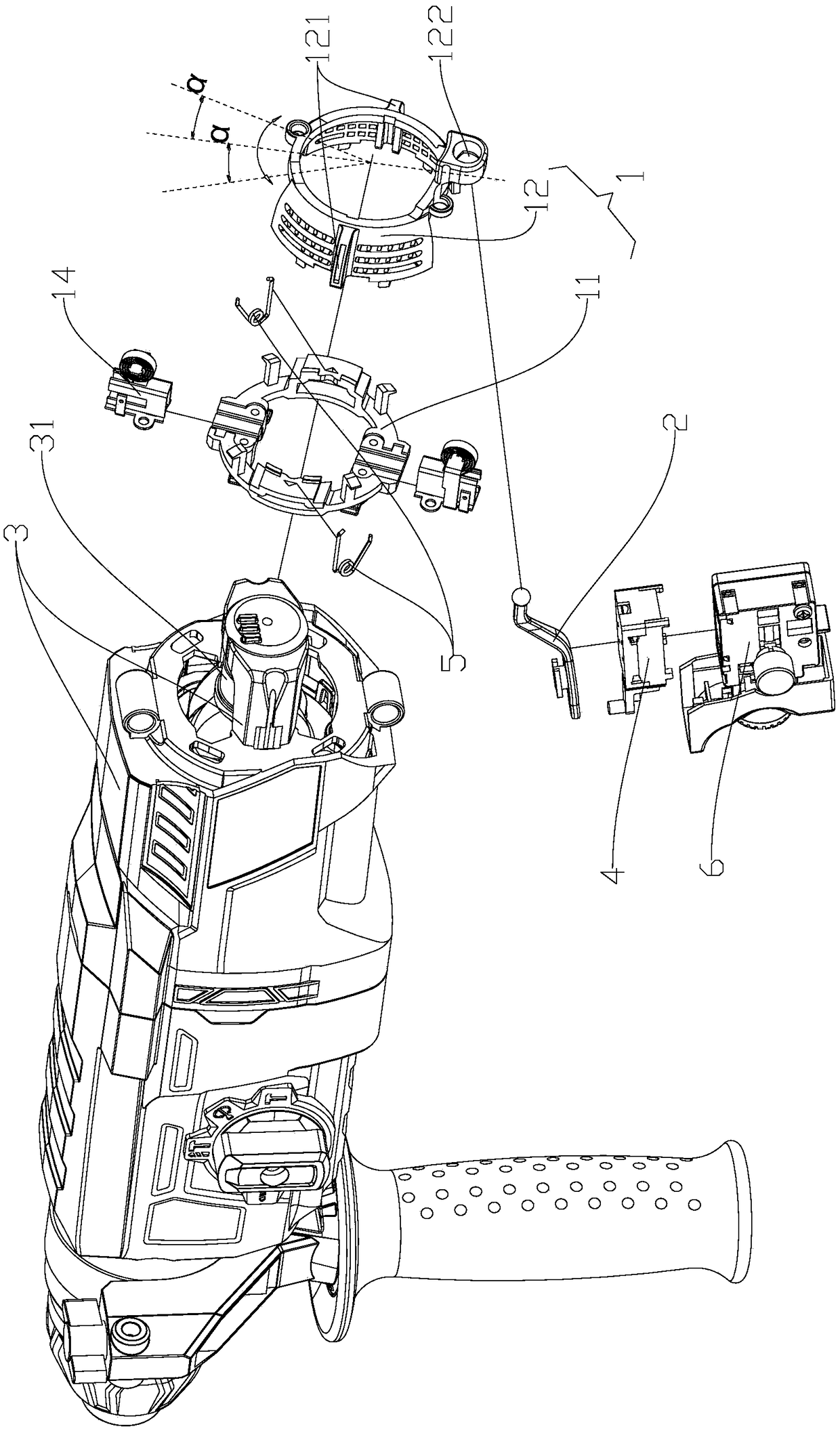
[0005] The current forward and reverse switching assembly is directly driven by the brush holder. The operator manually twists the brush holder. When the brush holder rotates, it drives the swing of the forward and reverse switching assembly itself, so the forward and reverse switching assembly itself pulls out. The rod must adopt an L-shaped structure, and the forward and reverse switching components can only be installed side by side with the brush holder, so it must be installed at the air inlet of the motor. point; and because the brush holder and the forward and reverse switching assembly itself have a certain thickness, the L-shaped pull rod of the forward and reverse switching assembly itself needs to be set to a relatively large length in order to be in contact with the brush holder, and the brush holder drives The L-shaped lever swings, and the L-shaped lever itself is a plastic part, which will produce a certain degree of bending deformation, and cannot be accurately and quickly positioned when switching between forward and reverse
[0006] For those skilled in the art, how to avoid the impact of air intake impurities on the forward and reverse switch components is a technical problem that needs to be solved at present

Method used


Image

  • A forward and reverse switching device and a single-phase series motor
  • A forward and reverse switching device and a single-phase series motor
  • A forward and reverse switching device and a single-phase series motor

Examples


Embodiment Construction

[0042] The core of the present invention is to provide a forward and reverse switching device, which improves the trigger structure of the forward and reverse components, and does not need to be arranged at the air inlet, so as to avoid the influence of the impurities in the intake air on the forward and reverse switch components.

[0043] In order to enable those skilled in the art to better understand the technical solution of the present invention, the forward and reverse switching device and the single-phase series motor of the present invention will be described in detail below in conjunction with the accompanying drawings and specific implementation methods.

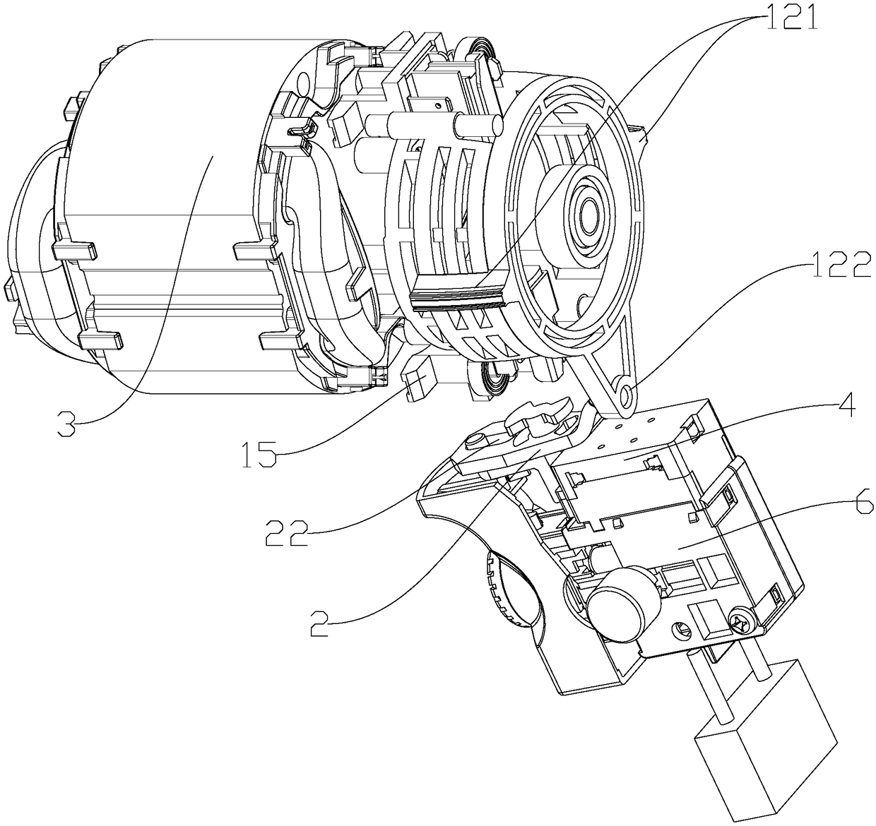
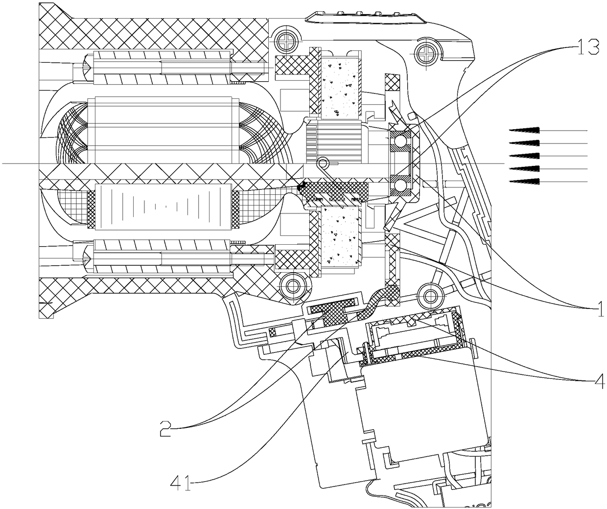
[0044] Such as Figure 1A As shown, it is an exploded view of the relative positions of each component of the forward and reverse switching device provided by the present invention and the motor, Figure 1B The overall structural diagram of the mutual assembly of the forward and reverse switching device and the moto...


PUM


Abstract

The invention discloses a forward and reverse switching device, wherein the carbon brush module can rotate clockwise and counterclockwise with respect to the chassis; The middle part of the reversingrod is rotatably connected to the chassis, the first end of the reversing rod is rotated by the carbon brush module, The second end of the commutation pull-out lever is in contact with and matched with the positive and negative swing lever of the positive and negative swing switching assembly, and the second end of the commutation pull-out lever can drive the positive and negative swing lever to swing, so that the positive and negative swing lever swings downward and backward, and the conductive loop of the motor lead connecting the plug in the positive and negative swing switching assembly ischanged, and the direction of the current is changed to realize commutation. Between that carbon brush module and the forward and reverse assembly, A forward and reverse assembly need not be providedat the air inlet, The invention effectively solves the contact ignition failure caused by the exposure of the contact point changing the current direction, the insufficient rigidity of the contact piece at the contact end, the plastic melting of the positioning base, the poor contact after the dust piles up for a long time, and improves the commutation stability in the bad working environment ofthe electric tool with high dust and strong vibration.

Description

technical field [0001] The invention relates to the technical field of electric tools, and further relates to a forward and reverse switching device. In addition, the invention also relates to a single-phase series motor. Background technique [0002] Motors can be divided into DC motors and AC motors due to different input currents. Motors driven by DC currents are called DC motors. DC motors can be divided into series-excited motors and split-excited motors due to the different connection methods between the magnetic field circuit and the armature circuit. Electric motors, re-excited motors; motors that use alternating current to rotate are called alternating current motors. [0003] The excitation winding of the DC series motor is connected in series with the rotor winding through the brush and the commutator, the excitation current is proportional to the armature current, the magnetic flux of the stator increases with the increase of the excitation current, and the torq...

Claims


Application Information

Patent Timeline
IPC IPC(8): H02K23/08
CPCH02K23/08
Inventor 王腾达安刚利严世良李小健
Owner 金华市聚杰电器有限公司
Learn More