A standing wave type stepping ultrasonic motor and a control method thereof

A technology of ultrasonic motor and control method, applied in the direction of generator/motor, piezoelectric effect/electrostrictive or magnetostrictive motor, electrical components, etc., can solve problems such as complex motor control structure, and achieve simplified stepping motion Effect

Inactive Publication Date: 2019-01-18
SOUTHEAST UNIV
View PDF1 Cites 0 Cited by
  • Summary
  • Abstract
  • Description
  • Claims
  • Application Information

AI Technical Summary

Problems solved by technology

In the stepping control system of the traditional ultrasonic motor, like the stepping motor, the sensor must be introd

Method used


Image

  • A standing wave type stepping ultrasonic motor and a control method thereof
  • A standing wave type stepping ultrasonic motor and a control method thereof
  • A standing wave type stepping ultrasonic motor and a control method thereof

Examples


Embodiment Construction

[0020] The technical solutions of the present invention will be further described below in conjunction with the accompanying drawings and embodiments.

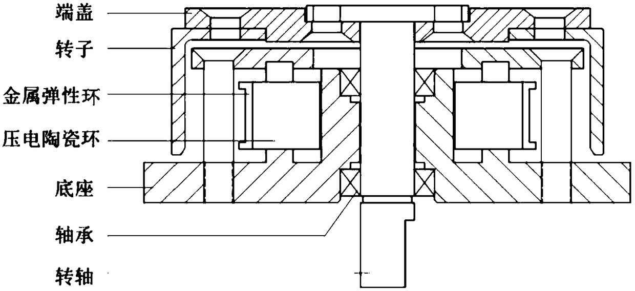
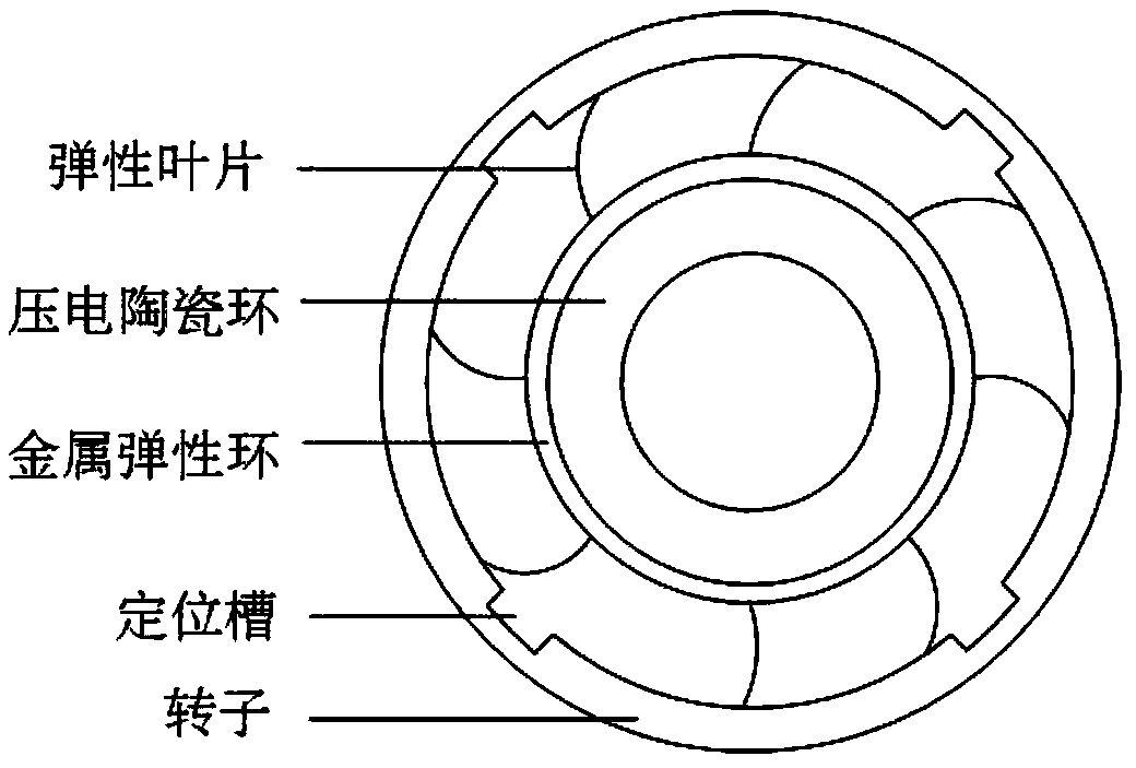
[0021] Such as figure 1 and figure 2 As shown, the standing wave stepping ultrasonic motor of the present invention includes a stator, a rotor, a rotating shaft, a bearing, an end cover and a base.

[0022] The stator structure is composed of a piezoelectric ceramic ring, a metal elastic ring and a number of elastic blades. The metal elastic ring and the piezoelectric ceramic ring are fixed by glue. The piezoelectric ceramic ring is inside the stator and occupies most of the volume of the stator, so the motor has relatively large energy. density. The elastic blade is fixed on the outside of the metal elastic ring by welding, and the angle between the normal line of the fixed point of the elastic blade and its angle is guaranteed to be between 25-35 degrees, and the elastic blade is evenly distributed on the outer ring of th...


PUM

PropertyMeasurementUnit
Angleaaaaaaaaaa

Abstract

The invention discloses a standing wave type stepping ultrasonic motor and a control method thereof. The structure of the standing wave type stepping ultrasonic motor comprises a stator, a rotor, a bearing, a rotating shaft, an end cover and a base. The stator structure comprises a metal elastic ring, a piezoelectric ceramic ring and an elastic blade. The rotor is cylindrical and has a plurality of positioning grooves with the same shape and width. a single-phase voltage of a certain frequency is applied to the motor, The rotor of the motor is driven to rotate by the radial vibration of the piezoelectric ceramic, the motor stops running when the rotor is stuck in the positioning groove, a high pulse voltage is continuously applied, the rotor continues to rotate out of the positioning groove, and at this time, the single-phase voltage is reapplied so that the motor can continue to run to the next positioning groove, thereby realizing the step operation in the case of an open loop. Compared with the traditional ultrasonic motor, the motor of the invention is simple in structure and small in volume, and realizes the step operation under the open loop control.

Description


Claims


Application Information

Patent Timeline
Owner SOUTHEAST UNIV
Why Eureka
Try Eureka